Factores que causan temperatura desigual dentro de la cámara de prueba de calor húmedo de alta y baja temperaturaEl cámara de prueba de calor húmedo de alta y baja temperatura es el equipo principal en pruebas ambientales de temperatura y humedad, utilizado principalmente para realizar pruebas de temperatura y humedad altas y bajas para evaluar la resistencia a la temperatura y la humedad de los productos, a fin de garantizar que nuestros productos puedan funcionar y operar normalmente bajo cualquier condición ambiental. Sin embargo, si la uniformidad de la temperatura excede el rango de desviación permitido durante las pruebas ambientales en la cámara de prueba de calor húmedo de alta y baja temperatura, los datos obtenidos de la prueba no son confiables y no pueden usarse como la tolerancia máxima para las pruebas de materiales o temperaturas altas y bajas. productos. Entonces, ¿cuáles son las razones que pueden hacer que la uniformidad de la temperatura exceda el rango de desviación permitido?1. Las diferencias en los objetos de prueba en la cámara de prueba de calor húmedo de alta y baja temperatura: si se colocan suficientes muestras de prueba que afectan la convección de calor interna general en la cámara de prueba de alta y baja temperatura, inevitablemente afectará la uniformidad del interior. temperatura hasta cierto punto, es decir, la uniformidad de la temperatura. Por ejemplo, si se colocan productos de iluminación LED, los propios productos emiten luz y calor, convirtiéndose en una carga térmica, que tiene un impacto significativo en la uniformidad de la temperatura.2. Los problemas de diseño dificultan lograr una estructura simétrica uniforme en la estructura interna y el espacio de la cámara de prueba de calor húmedo de alta y baja temperatura, y una estructura asimétrica conducirá inevitablemente a desviaciones en la uniformidad de la temperatura interna. Este aspecto se refleja principalmente en el diseño y procesamiento de la chapa, como el diseño de los conductos de aire, la ubicación de las tuberías de calefacción y el tamaño de la potencia del ventilador. Todo esto afectará la uniformidad de la temperatura dentro de la caja.3. Debido a las diferentes estructuras de la pared interior de la cámara de prueba de calor húmedo de alta y baja temperatura, la temperatura de la pared interior de la cámara de prueba también será desigual, lo que afectará la convección de calor dentro de la cámara de trabajo y provocará una desviación. en la uniformidad de la temperatura interna.4. Debido a los diferentes coeficientes de transferencia de calor en las superficies frontal, posterior, izquierda, derecha, superior e inferior de la pared de la caja en el estudio, algunas tienen orificios para roscar, orificios de detección, orificios de prueba, etc., que causan calor local. disipación y transferencia, lo que resulta en una distribución desigual de la temperatura del cuerpo de la caja y una transferencia de calor por convección radiativa desigual en la pared de la caja, lo que afecta la uniformidad de la temperatura.5. El sellado de la caja y la puerta no es estricto, por ejemplo, la tira de sellado no está personalizada y tiene costuras, y la puerta pierde aire, lo que afecta la uniformidad de la temperatura del espacio de trabajo.6. Si el volumen del objeto de prueba es demasiado grande, o si la posición o el método para colocar el objeto de prueba en la cámara de prueba de calor húmedo de alta y baja temperatura es inadecuado, obstruirá la convección del aire en el interior y también provocará una uniformidad de temperatura significativa. desviación. Colocar el producto de prueba junto al conducto de aire afecta seriamente la circulación del aire y, por supuesto, la uniformidad de la temperatura se verá muy afectada.En resumen, todos estos puntos son los principales culpables que afectan la uniformidad de la temperatura dentro de la cámara de prueba de calor húmedo de alta y baja temperatura. Esperamos que todos puedan investigar uno por uno estos aspectos, lo que seguramente solucionará sus confusiones y dificultades.Estimado cliente:Hola, nuestra empresa es un equipo de desarrollo de alta calidad con una sólida solidez técnica, que brinda productos de alta calidad, soluciones completas y excelentes servicios técnicos a nuestros clientes. Los principales productos incluyen cámaras de prueba de temperatura y humedad constantes sin cita previa, Máquinas de prueba de envejecimiento acelerado UV, cámaras de prueba de cambio rápido de temperatura, cámaras de pruebas ambientales sin cita previa, probadores de envejecimiento UV, cámaras de temperatura y humedad constantes, etc. Nuestra empresa se adhiere al principio de construir un negocio con integridad, mantener la calidad y esforzarse por lograr el progreso. Con un ritmo más decidido, escalamos continuamente nuevas alturas y contribuimos a la industria nacional de automatización. Damos la bienvenida a clientes nuevos y antiguos para que elijan con confianza los productos que les gustan. ¡Le atenderemos de todo corazón!
Las perspectivas de desarrollo de las cámaras de prueba de calor húmedo de alta y baja temperatura son prometedorasHoy en día, la industria de equipos de pruebas ambientales de China se está desarrollando rápidamente, innovando y superándose constantemente. Sin embargo, en comparación con el nivel internacional, China sólo ha alcanzado el nivel técnico de mediados de los años noventa. El desarrollo de equipos de prueba industriales modernos no solo depende del nivel de tecnología del producto, sino que también implica tecnología de aplicación de ingeniería. Pero muchos productos en nuestro país ya han alcanzado el nivel de los productos convencionales internacionales, con una amplia variedad, especificaciones completas, precios bajos y son muy competitivos en el mercado internacional; Por ejemplo, la cámara de prueba de calor húmedo de alta y baja temperatura ha alcanzado el nivel de producto internacional.La cámara de prueba de calor húmedo de alta y baja temperatura en China ha obtenido muy buenos resultados tanto en términos de confiabilidad como de precisión del producto. Ahora la cámara de pruebas en China se está volviendo cada vez más inteligente y está integrada a Internet. Siempre que tengas una computadora, podrás controlarla en cualquier lugar y en cualquier momento; Y el precio es relativamente más barato en comparación con países extranjeros, con la misma calidad pero diferentes precios. Sin embargo, todavía es necesario innovar constantemente en indicadores tecnológicos, superarse constantemente y convertirse en líder en equipos de pruebas ambientales. Desde la perspectiva actual, el camino de desarrollo de las cámaras de prueba de calor húmedo de alta y baja temperatura es brillante.Por otro lado, la industria china de equipos de pruebas ambientales se está acelerando desde los laboratorios hasta la vanguardia de la producción y hasta los hogares y las vidas de las personas. Se están desarrollando grandes cantidades de instrumentos portátiles, portátiles y personalizados, y las pruebas de productos básicos, las pruebas ambientales y las pruebas de salud se han convertido en nuevos puntos críticos de demanda; La tendencia actual en el desarrollo de instrumentos y contadores va en aumento. Se cree que pronto, el producto líder de China en la industria de pruebas ambientales, la cámara de prueba de calor húmedo de alta y baja temperatura, estará muy por delante en términos de tecnología, marca y otros aspectos a nivel internacional.Estimado cliente:Hola, nuestra empresa es un equipo de desarrollo de alta calidad con una sólida solidez técnica, que brinda productos de alta calidad, soluciones completas y excelentes servicios técnicos a nuestros clientes. Los principales productos incluyen cámaras de prueba de temperatura y humedad constantes, máquinas de prueba de envejecimiento acelerado por UV, cámaras de prueba de cambio rápido de temperatura, cámaras de pruebas ambientales sin cita previa, probadores de envejecimiento UV, cámaras de temperatura y humedad constantes, etc. Nuestra empresa se adhiere al principio de construir un negocio con integridad, mantener la calidad y esforzarse por lograr el progreso. Con un ritmo más decidido, escalamos continuamente nuevas alturas y contribuimos a la industria nacional de automatización. Damos la bienvenida a clientes nuevos y antiguos para que elijan con confianza los productos que les gustan. ¡Le atenderemos de todo corazón!
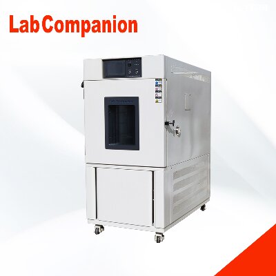
Características estructurales de la cámara de pruebas de control de temperatura y humedad.Adecuado para diversos pequeños aparatos eléctricos, instrumentos, materiales y componentes para pruebas de calor húmedo, también es adecuado para realizar pruebas de envejecimiento. Esta cámara de prueba adopta la estructura más razonable y el método de control estable y confiable actualmente disponible, lo que la hace estéticamente agradable, fácil de operar, segura y con alta precisión en el control de temperatura y humedad. Es un equipo ideal para realizar pruebas de temperatura y humedad constantes.(1) El cuerpo de la caja de prueba tiene la forma de una estructura integral, con el sistema de refrigeración ubicado en la parte inferior trasera de la caja y el sistema de control ubicado en la parte superior de la caja de prueba.(2) Dentro de la capa intermedia del conducto de aire en un extremo del estudio, hay dispositivos tales como calentadores, evaporadores de refrigeración y aspas de ventilador distribuidos; En el lado izquierdo de la caja de prueba, hay un orificio para cable de Ø 50 y la caja de prueba es una puerta única (manija de puerta integrada de acero inoxidable)(3) El sello de caucho de silicona antienvejecimiento y de alta temperatura de doble capa puede garantizar eficazmente la pérdida de temperatura de la cámara de prueba.(4) Hay ventanas de observación, dispositivos de prevención de heladas y accesorios de iluminación conmutables en la puerta de la caja. La ventana de observación adopta vidrio templado hueco de múltiples capas y la película conductora de la lámina adhesiva interna se calienta y descongela. Los accesorios de iluminación adoptan lámparas Philips de marca importada, que pueden observar eficazmente los cambios experimentales en el estudio desde todos los ángulos.El ciclo de refrigeración de la caja de control de temperatura y humedad adopta el ciclo de Carnot inverso, que consta de dos procesos isotérmicos y dos procesos adiabáticos. El proceso es el siguiente: el compresor comprime adiabáticamente el refrigerante a una presión más alta y el trabajo consumido aumenta la temperatura de escape. Luego, el refrigerante intercambia calor con el medio circundante a través del condensador y transfiere calor al medio circundante. Después de que el refrigerante sufre una expansión adiabática a través de la válvula de cierre, la temperatura del refrigerante disminuye. Finalmente, el refrigerante absorbe calor del objeto a una temperatura más alta a través del evaporador, lo que hace que la temperatura del objeto enfriado disminuya. Este ciclo se repite para lograr el objetivo de enfriarse.El diseño del sistema de refrigeración de esta cámara de prueba aplica tecnología de regulación de energía, que puede garantizar el funcionamiento normal de la unidad de refrigeración y ajustar eficazmente el consumo de energía y la capacidad de refrigeración del sistema de refrigeración, para mantener el sistema de refrigeración en el estado operativo óptimo. Al utilizar el control de temperatura equilibrada (BTC), el sistema de control calcula automáticamente la salida del calentador en función del punto de temperatura establecido mediante el cálculo PID cuando el sistema de refrigeración funciona de forma continua, logrando en última instancia un equilibrio dinámico.Estimado cliente: Hola, nuestra empresa es un equipo de desarrollo de alta calidad con una sólida solidez técnica, que brinda productos de alta calidad, soluciones completas y excelentes servicios técnicos a nuestros clientes. Los principales productos incluyen cámaras de prueba de temperatura y humedad constantes sin cita previa, Máquinas de prueba de envejecimiento acelerado UV, cámaras de prueba de cambio rápido de temperatura, cámaras de pruebas ambientales sin cita previa, probadores de envejecimiento UV, cámaras de temperatura y humedad constantes, etc. Nuestra empresa se adhiere al principio de construir un negocio con integridad, mantener la calidad y esforzarse por lograr el progreso. Con un ritmo más decidido, escalamos continuamente nuevas alturas y contribuimos a la industria nacional de automatización. Damos la bienvenida a clientes nuevos y antiguos para que elijan con confianza los productos que les gustan. ¡Le atenderemos de todo corazón!
Condiciones de servicio para cámaras de prueba de alta, baja temperatura y baja presión.Una de las condiciones de uso para cámaras de prueba de alta, baja temperatura y baja presión: condiciones ambientalesa、 Temperatura: 15 ℃ ~ 35 ℃;b 、 Humedad relativa: no superior al 85%;c 、 Presión atmosférica: 80 kPa ~ 106 kPad、 No hay vibraciones fuertes ni gases corrosivos en el área circundante;e、 No exponerse directamente a la luz solar ni a la radiación directa de otras fuentes de frío o calor;f、 No hay un flujo de aire fuerte alrededor, y cuando es necesario forzar el flujo de aire circundante, el flujo de aire no debe soplarse directamente sobre la caja;g、 La influencia del campo magnético en el circuito de control de la caja de prueba libre de interferencias en el área circundante;h、 No hay altas concentraciones de polvo o sustancias corrosivas en el área circundante.Condición 2 para el uso de cámaras de prueba de alta, baja temperatura y baja presión: Condiciones de suministro de energíaa、 Voltaje CA: 220 V ± 22 V o 380 V ± 38 V;b 、 Frecuencia: 50 HZ ± 0,5 HZCondición tres para el uso de cámaras de prueba de alta, baja temperatura y baja presión: condiciones del suministro de aguaEs recomendable utilizar agua del grifo o agua circulante que cumpla las siguientes condiciones:a、 Temperatura del agua: no superior a 30 ℃;b 、 Presión del agua: 0,1 MPa ~ 0,3 MPa;c、 Calidad del agua: cumple con los estándares de agua industrial.Condición 4 para el uso de cámaras de prueba de alta, baja temperatura y baja presión: Condiciones de carga de pruebaLa carga de la cámara de pruebas debe cumplir las siguientes condiciones cada semana:a 、 La masa total de la carga no deberá exceder los 80 kg por metro cúbico dentro del volumen de la cámara de trabajo.b 、 El volumen total de la carga no excederá 5/1 del volumen de la cámara de trabajo.c、 En cualquier sección transversal perpendicular a la dirección predominante del viento, la suma de las áreas de carga no debe exceder 3/1 del área de la sección transversal de la cámara de trabajo en ese lugar, y la carga no debe obstruir el flujo de aire. cuando se coloca.Estimado cliente:Nuestra empresa cuenta con productos tales como cámaras de prueba de cambio rápido de temperatura, máquinas de prueba de resistencia a la intemperie aceleradas por rayos UV y cámaras de control de temperatura y humedad. Puede llamar a nuestra línea directa de servicio a través de nuestro sitio web para obtener más información sobre nuestros productos. Nuestra búsqueda es interminable y damos la bienvenida a clientes nuevos y antiguos para que elijan sus productos favoritos con confianza. ¡Estaremos dedicados a servirle!
El cuadro de prueba del entorno de selección de usuario debe leer1. Criterios de selección de equipos.Actualmente no existe un número exacto de factores ambientales naturales y factores ambientales inducidos que existen en la superficie de la Tierra y en la atmósfera, entre los cuales hay nada menos que una docena de factores que tienen un impacto significativo en el uso y la vida útil de los productos de ingeniería. (equipo). Los ingenieros dedicados al estudio de las condiciones ambientales para productos de ingeniería han compilado y resumido las condiciones ambientales que existen en la naturaleza y son inducidas por las actividades humanas en una serie de estándares y especificaciones de prueba para guiar las pruebas ambientales y de confiabilidad de los productos de ingeniería. Por ejemplo, GJB150, la norma militar nacional de la República Popular China para pruebas ambientales de equipos militares, y GB2423, la norma nacional de la República Popular China para pruebas ambientales de productos eléctricos y electrónicos, que orienta las pruebas ambientales de productos eléctricos y electrónicos. productos electrónicos. Por lo tanto, la base principal para seleccionar equipos de prueba ambientales y de confiabilidad son las especificaciones y estándares de prueba de los productos de ingeniería.En segundo lugar, para estandarizar la tolerancia de las condiciones de pruebas ambientales en equipos experimentales y garantizar la precisión del control de los parámetros ambientales, las agencias nacionales de supervisión técnica y varios departamentos industriales también han formulado una serie de regulaciones de calibración para equipos de pruebas ambientales e instrumentos de detección. Como la norma nacional GB5170 de la República Popular de China "Método de calibración de parámetros básicos para equipos de prueba ambiental de productos eléctricos y electrónicos" y JJG190-89 "Regulaciones de calibración de prueba para sistemas de banco de pruebas de vibración eléctrica" emitidas e implementadas por la Administración Estatal de Supervisión Técnica. Estas regulaciones de verificación también son una base importante para seleccionar equipos de prueba ambientales y de confiabilidad. No se permite la puesta en uso de equipos de prueba que no cumplan con los requisitos de estas normas de verificación.2. Principios básicos para la selección de equipos.La selección de equipos de pruebas ambientales y de confiabilidad debe seguir los siguientes cinco principios básicos:1. Reproducibilidad de las condiciones ambientales.Es imposible reproducir completa y exactamente en el laboratorio las condiciones ambientales que existen en la naturaleza. Sin embargo, dentro de un cierto rango de tolerancia, las personas pueden simular de manera precisa y aproximada las condiciones ambientales externas que experimentan los productos de ingeniería durante el uso, almacenamiento, transporte y otros procesos. Este pasaje se puede resumir en lenguaje de ingeniería de la siguiente manera: "Las condiciones ambientales (incluido el entorno de la plataforma) creadas por el equipo de prueba alrededor del producto probado deben cumplir con los requisitos de las condiciones ambientales y sus tolerancias especificadas en las especificaciones de prueba del producto. La caja de temperatura Los utilizados para pruebas de productos militares no solo deben cumplir con los requisitos de las normas militares nacionales GJB150.3-86 y GJB150.4-86 para diferentes uniformidades y precisión del control de temperatura. Sólo de esta manera se puede garantizar la reproducibilidad de las condiciones ambientales en las pruebas ambientales. .2. Repetibilidad de las condiciones ambientales.Se puede utilizar un equipo de pruebas ambientales para múltiples pruebas del mismo tipo de producto, y un producto de ingeniería probado también se puede probar en diferentes equipos de pruebas ambientales. Para garantizar la comparabilidad de los resultados de las pruebas obtenidos para el mismo producto en las mismas condiciones de prueba ambientales especificadas en las especificaciones de prueba, es necesario exigir que las condiciones ambientales proporcionadas por el equipo de prueba ambiental sean reproducibles. Esto significa que los niveles de tensión (como tensión térmica, tensión por vibración, tensión eléctrica, etc.) aplicados por el equipo de pruebas ambientales al producto probado son consistentes con los requisitos de la misma especificación de prueba.La repetibilidad de las condiciones ambientales proporcionadas por los equipos de pruebas ambientales está garantizada por el departamento nacional de verificación metrológica después de pasar la verificación de acuerdo con las normas de verificación formuladas por la agencia nacional de supervisión técnica. Por lo tanto, es necesario exigir que el equipo de prueba ambiental cumpla con los requisitos de varios indicadores técnicos e indicadores de precisión en las regulaciones de calibración, y que no exceda el límite de tiempo especificado en el ciclo de calibración en términos de tiempo de uso. Si se utiliza una mesa de vibración eléctrica muy común, además de cumplir con indicadores técnicos como fuerza de excitación, rango de frecuencia y capacidad de carga, también debe cumplir con los requisitos de indicadores de precisión como relación de vibración lateral, uniformidad de aceleración de la mesa y distorsión armónica. especificado en el reglamento de calibración. Además, la vida útil después de cada calibración es de dos años, y después de dos años, se debe recalibrar y calificar antes de ponerlo en uso.3. Mensurabilidad de los parámetros de las condiciones ambientales.Las condiciones ambientales proporcionadas por cualquier equipo de prueba ambiental deben ser observables y controlables. Esto no solo es para limitar los parámetros ambientales dentro de un cierto rango de tolerancia y garantizar la reproducibilidad y repetibilidad de las condiciones de prueba, sino que también es necesario para la seguridad de las pruebas del producto, a fin de evitar daños al producto probado causados por condiciones ambientales no controladas y pérdidas innecesarias. En la actualidad, varios estándares experimentales generalmente requieren que la precisión de las pruebas de parámetros no sea inferior a un tercio del error permitido en condiciones experimentales.4. Exclusión de condiciones de prueba ambientales.Cada vez que se realiza una prueba ambiental o de confiabilidad, existen regulaciones estrictas sobre la categoría, magnitud y tolerancia de los factores ambientales, y los factores ambientales que no requieren prueba están excluidos de penetrar en ella, con el fin de proporcionar una base definitiva para juzgar y analizar. Fallo del producto y modos de fallo durante o después de la prueba. Por lo tanto, se requiere que el equipo de pruebas ambientales no sólo proporcione las condiciones ambientales especificadas, sino que tampoco permita que se agregue ninguna otra interferencia de estrés ambiental al producto probado. Como se define en las regulaciones de verificación para mesas de vibración eléctrica, el flujo magnético de fuga de la mesa, la relación señal-ruido de aceleración y la relación del valor cuadrático medio total de la aceleración dentro y fuera de la banda. Los indicadores de precisión, como la verificación de señales aleatorias y la distorsión armónica, se establecen como elementos de verificación para garantizar la singularidad de las condiciones de prueba ambientales.5. Seguridad y confiabilidad de los equipos experimentales.Las pruebas ambientales, especialmente las pruebas de confiabilidad, tienen un ciclo de prueba largo y, a veces, se dirigen a productos militares de alto valor. Durante el proceso de prueba, el personal de pruebas a menudo necesita operar, inspeccionar o realizar pruebas en el sitio. Por lo tanto, se requiere que el equipo de pruebas ambientales tenga las características de operación segura, operación conveniente, uso confiable y larga vida útil para garantizar el progreso normal de las pruebas en sí. Los diversos dispositivos de protección, medidas de alarma y dispositivos de bloqueo de seguridad del equipo de prueba deben ser completos y confiables para garantizar la seguridad y confiabilidad del personal de prueba, los productos probados y el propio equipo de prueba.3 、 Selección de cámara de temperatura y humedad1. Selección de CapacidadAl colocar el producto de prueba (componentes, conjuntos, piezas o máquina completa) en una cámara climática para realizar la prueba, con el fin de garantizar que la atmósfera alrededor del producto de prueba pueda cumplir con las condiciones de prueba ambientales especificadas en las especificaciones de la prueba, las dimensiones de trabajo del La cámara climática y las dimensiones generales del producto de prueba deben seguir las siguientes normas:a) El volumen del producto probado (W × D × H) no debe exceder el (20-35) % del espacio de trabajo efectivo de la cámara de prueba (se recomienda el 20 %). Para productos que generan calor durante las pruebas, se recomienda utilizar no más del 10%.b) La relación entre el área de la sección transversal a barlovento del producto probado y el área total de la cámara de prueba en esa sección no debe exceder (35-50)% (se recomienda 35%).c) La distancia entre la superficie exterior del producto probado y la pared de la cámara de prueba debe mantenerse al menos entre 100 y 150 mm (se recomienda 150 mm).Las tres disposiciones anteriores son en realidad interdependientes y unificadas. Tomando como ejemplo una caja cúbica de 1 metro cúbico, una relación de área de 1: (0,35-0,5) equivale a una relación de volumen de 1: (0,207-0,354). Una distancia de 100-150 mm desde la pared de la caja equivale a una relación de volumen de 1: (0,343-0,512).En resumen, el volumen de la cámara de trabajo de la cámara de pruebas climáticas debe ser al menos de 3 a 5 veces el volumen externo del producto probado. Las razones para dictar dichas regulaciones son las siguientes:Después de colocar la pieza de prueba en la caja, ocupa el canal liso y el estrechamiento del canal provocará un aumento en la velocidad del flujo de aire. Acelere el intercambio de calor entre el flujo de aire y la pieza de prueba. Esto es incompatible con la reproducción de las condiciones ambientales, ya que las normas pertinentes estipulan que la velocidad del flujo de aire alrededor de la muestra de prueba en la cámara de prueba no debe exceder los 1,7 m/s para las pruebas de temperatura ambiental, con el fin de evitar que la muestra de prueba y la atmósfera circundante de generar una conducción de calor que no se corresponde con la realidad. Cuando está descargado, la velocidad media del viento dentro de la cámara de prueba es de 0,6 a 0,8 m/s, sin exceder 1 m/s. Cuando se cumple la relación de espacio y área especificada en los puntos a) y b), la velocidad del viento en el campo de flujo puede aumentar en un (50-100) %, con una velocidad máxima promedio del viento de (1-1,7) m/s. Cumplir con los requisitos especificados en las normas. Si el volumen o el área de la sección transversal a barlovento de la pieza de prueba se incrementa sin restricciones durante el experimento, la velocidad real del flujo de aire durante la prueba excederá la velocidad máxima del viento especificada en el estándar de prueba y se cuestionará la validez de los resultados de la prueba. .Los indicadores de precisión de los parámetros ambientales en la cámara de trabajo de la cámara climática, como temperatura, humedad, tasa de sedimentación de niebla salina, etc., se miden en condiciones sin carga. Una vez colocada la pieza de prueba, tendrá un impacto en la uniformidad de los parámetros ambientales en la cámara de trabajo de la cámara de prueba. Cuanto mayor sea el espacio ocupado por la pieza de prueba, más severo será este impacto. Los datos experimentales muestran que la diferencia de temperatura entre los lados de barlovento y sotavento en el campo de flujo puede alcanzar entre 3 y 8 ℃ y, en casos severos, puede llegar a 10 ℃ o más. Por lo tanto, es necesario cumplir los requisitos de a] y b] tanto como sea posible para garantizar la uniformidad de los parámetros ambientales alrededor del producto probado.Según el principio de conducción de calor, la temperatura del flujo de aire cerca de la pared de la caja suele ser de 2 a 3 ℃ diferente de la temperatura en el centro del campo de flujo, y puede incluso alcanzar los 5 ℃ en los límites superior e inferior de temperatura alta y baja. bajas temperaturas. La temperatura de la pared de la caja difiere de la temperatura del campo de flujo cerca de la pared de la caja en 2-3 ℃ (dependiendo de la estructura y el material de la pared de la caja). Cuanto mayor sea la diferencia entre la temperatura de prueba y el ambiente atmosférico externo, mayor será la diferencia de temperatura. Por lo tanto, el espacio dentro de una distancia de 100-150 mm desde la pared de la caja no se puede utilizar.2. Selección del rango de temperaturaEn la actualidad, el rango de temperatura de las cámaras de prueba en el extranjero es generalmente de -73 a +177 ℃, o de -70 a +180 ℃. La mayoría de los fabricantes nacionales generalmente operan entre -80 y +130 ℃, -60 y +130 ℃, -40 y +130 ℃, y también hay altas temperaturas de hasta 150 ℃. Estos rangos de temperatura normalmente pueden satisfacer las necesidades de pruebas de temperatura de la gran mayoría de productos militares y civiles en China. A menos que existan requisitos especiales, como productos instalados cerca de fuentes de calor como motores, el límite superior de temperatura no debe aumentarse ciegamente. Porque cuanto mayor sea la temperatura límite superior, mayor será la diferencia de temperatura entre el interior y el exterior de la caja y peor será la uniformidad del campo de flujo dentro de la caja. Cuanto más pequeño sea el tamaño del estudio disponible. Por otro lado, cuanto mayor sea el valor límite superior de temperatura, mayores serán los requisitos de resistencia al calor para los materiales aislantes (como la lana de vidrio) en la capa intermedia de la pared de la caja. Cuanto mayor sea el requisito de sellado de la caja, mayor será el coste de producción de la caja.3. Selección del rango de humedadLos indicadores de humedad proporcionados por las cámaras de pruebas ambientales nacionales y extranjeras son en su mayoría de 20-98% RH o 30-98% RH. Si la cámara de prueba de calor húmedo no tiene un sistema de deshumidificación, el rango de humedad es del 60 al 98 %. Este tipo de cámara de pruebas sólo puede realizar pruebas de alta humedad, pero su precio es mucho menor. Vale la pena señalar que después del índice de humedad se debe indicar el rango de temperatura correspondiente o temperatura mínima de punto de rocío. Debido a que la humedad relativa está directamente relacionada con la temperatura, para la misma humedad absoluta, cuanto mayor es la temperatura, menor es la humedad relativa. Por ejemplo, si la humedad absoluta es 5 g/Kg (refiriéndose a 5 g de vapor de agua en 1 kg de aire seco), cuando la temperatura es 29 ℃, la humedad relativa es 20% RH, y cuando la temperatura es 6 ℃, la humedad relativa la humedad es 90% HR. Cuando la temperatura cae por debajo de los 4 ℃ y la humedad relativa supera el 100%, se producirá condensación dentro de la caja.Para lograr altas temperaturas y humedad, simplemente rocíe vapor o gotas de agua atomizadas en el aire de la caja para humidificar. Las bajas temperaturas y la humedad son relativamente difíciles de controlar porque la humedad absoluta en este momento es muy baja, a veces mucho más baja que la humedad absoluta de la atmósfera. Es necesario deshumidificar el aire que circula dentro de la caja para que se seque. En la actualidad, la gran mayoría de cámaras de temperatura y humedad tanto a nivel nacional como internacional adoptan el principio de refrigeración y deshumidificación, que implica añadir un conjunto de tubos de luz de refrigeración a la sala de aire acondicionado de la cámara. Cuando el aire húmedo pasa a través de una tubería fría, su humedad relativa alcanzará el 100 % de humedad relativa, ya que el aire se satura y se condensa en la tubería de luz, lo que hace que el aire sea más seco. En teoría, este método de deshumidificación puede alcanzar temperaturas de punto de rocío por debajo de cero grados, pero cuando la temperatura de la superficie del punto frío alcanza los 0 ℃, las gotas de agua condensadas en la superficie del tubo de luz se congelarán, afectando el intercambio de calor en la superficie de la luz. tubería y reduciendo la capacidad de deshumidificación. Además, debido a que la caja no se puede sellar completamente, el aire húmedo de la atmósfera se filtrará dentro de la caja, lo que provocará que aumente la temperatura del punto de rocío. Por otro lado, el aire húmedo que fluye entre los tubos de luz solo alcanza la saturación en el momento del contacto con los tubos de luz (puntos fríos) y libera vapor de agua, por lo que este método de deshumidificación es difícil de mantener la temperatura del punto de rocío dentro de la caja debajo. 0 ℃. La temperatura mínima real del punto de rocío alcanzada es de 5-7 ℃. Una temperatura de punto de rocío de 5 ℃ equivale a un contenido de humedad absoluta de 0,0055 g/kg, correspondiente a una humedad relativa del 20 % RH a una temperatura de 30 ℃. Si se requiere una temperatura de 20 ℃ y una humedad relativa del 20% RH, con una temperatura de punto de rocío de -3 ℃, es difícil utilizar refrigeración para la deshumidificación y se debe seleccionar un sistema de secado de aire para lograrlo.4. Selección del modo de control.Hay dos tipos de cámaras de prueba de temperatura y humedad: cámara de prueba constante y cámara de prueba alterna.La cámara de prueba ordinaria de alta y baja temperatura generalmente se refiere a una cámara de prueba de alta y baja temperatura constante, que se controla estableciendo una temperatura objetivo y tiene la capacidad de mantener automáticamente una temperatura constante hasta el punto de temperatura objetivo. El método de control de la cámara de prueba de temperatura y humedad constantes también es similar: establece un punto de temperatura y humedad objetivo, y la cámara de prueba tiene la capacidad de mantener automáticamente una temperatura constante hasta el punto de temperatura y humedad objetivo. La cámara de prueba alterna de temperatura alta y baja tiene uno o más programas para configurar cambios y ciclos de temperatura alta y baja. La cámara de prueba tiene la capacidad de completar el proceso de prueba de acuerdo con la curva preestablecida y puede controlar con precisión las velocidades de calentamiento y enfriamiento dentro del rango máximo de capacidad de velocidad de calentamiento y enfriamiento, es decir, las velocidades de calentamiento y enfriamiento se pueden controlar de acuerdo con la pendiente de la curva establecida. De manera similar, la cámara de prueba de humedad alterna de temperatura alta y baja también tiene curvas de temperatura y humedad preestablecidas, y la capacidad de controlarlas de acuerdo con lo preestablecido. Por supuesto, las cámaras de prueba alternas tienen la función de cámaras de prueba constantes, pero el costo de fabricación de las cámaras de prueba alternas es relativamente alto porque necesitan estar equipadas con dispositivos de registro automático de curvas, controladores de programa y resolver problemas como encender la máquina de refrigeración. cuando la temperatura en la sala de trabajo es alta. Por lo tanto, el precio de las cámaras de prueba alternas es generalmente más de un 20% más alto que el de las cámaras de prueba constantes. Por lo tanto, debemos tomar como punto de partida la necesidad de métodos experimentales y elegir una cámara de prueba constante o una cámara de prueba alterna.5. Selección de tasa de temperatura variable.Las cámaras de prueba ordinarias de alta y baja temperatura no tienen un indicador de velocidad de enfriamiento y el tiempo desde la temperatura ambiente hasta la temperatura nominal más baja es generalmente de 90 a 120 minutos. La cámara de prueba alterna de temperatura alta y baja, así como la cámara de prueba de calor húmedo alternante de temperatura alta y baja, tienen requisitos de velocidad de cambio de temperatura. Generalmente se requiere que la velocidad de cambio de temperatura sea de 1 ℃/min, y la velocidad se puede ajustar dentro de este rango de velocidad. La cámara de prueba de cambio rápido de temperatura tiene una velocidad de cambio de temperatura rápida, con velocidades de calentamiento y enfriamiento que varían de 3 ℃/min a 15 ℃/min. En ciertos rangos de temperatura, las velocidades de calentamiento y enfriamiento pueden incluso alcanzar más de 30 ℃/min.El rango de temperatura de varias especificaciones y velocidades de las cámaras de prueba de cambio rápido de temperatura es generalmente el mismo, es decir, -60 a +130 ℃. Sin embargo, el rango de temperatura para evaluar la velocidad de enfriamiento no es el mismo. De acuerdo con los diferentes requisitos de prueba, el rango de temperatura de las cámaras de prueba de cambio rápido de temperatura es de -55 a +80 ℃, mientras que otras son de -40 a +80 ℃.Hay dos métodos para determinar la tasa de cambio de temperatura de la cámara de prueba de cambio rápido de temperatura: uno es la tasa promedio de aumento y caída de temperatura durante todo el proceso, y el otro es la tasa lineal de aumento y caída de temperatura (en realidad, la velocidad promedio cada 5 minutos). La velocidad media a lo largo de todo el proceso se refiere a la relación entre la diferencia entre las temperaturas más alta y más baja dentro del rango de temperatura de la cámara de prueba y el tiempo. En la actualidad, los parámetros técnicos de la tasa de cambio de temperatura proporcionados por varios fabricantes de equipos de pruebas ambientales en el extranjero se refieren a la tasa promedio durante todo el proceso. La tasa lineal de aumento y caída de temperatura se refiere a la tasa de cambio de temperatura garantizada dentro de cualquier período de 5 minutos. De hecho, para la cámara de prueba de cambio rápido de temperatura, la etapa más difícil y crítica para garantizar la velocidad lineal de aumento y caída de la temperatura es la velocidad de enfriamiento que la cámara de prueba puede alcanzar durante los últimos 5 minutos del período de enfriamiento. Desde cierta perspectiva, la velocidad lineal de calentamiento y enfriamiento (velocidad promedio cada 5 minutos) es más científica. Por lo tanto, lo mejor es que el equipo experimental tenga dos parámetros: la velocidad promedio de aumento y caída de temperatura durante todo el proceso y la velocidad lineal de aumento y caída de temperatura (velocidad promedio cada 5 minutos). En términos generales, la velocidad lineal de calentamiento y enfriamiento (velocidad promedio cada 5 minutos) es la mitad de la velocidad promedio de calentamiento y enfriamiento durante todo el proceso.6. Velocidad del vientoSegún las normas pertinentes, la velocidad del viento dentro de la cámara de temperatura y humedad durante las pruebas ambientales debe ser inferior a 1,7 m/s. Para la prueba en sí, cuanto menor sea la velocidad del viento, mejor. Si la velocidad del viento es demasiado alta, acelerará el intercambio de calor entre la superficie de la pieza de prueba y el flujo de aire dentro de la cámara, lo que no favorece la autenticidad de la prueba. Pero para garantizar la uniformidad dentro de la cámara de prueba, es necesario que circule aire dentro de la cámara de prueba. Sin embargo, para cámaras de prueba de cambio rápido de temperatura y cámaras de prueba ambientales integrales con múltiples factores como temperatura, humedad y vibración, para lograr la tasa de cambio de temperatura, es necesario acelerar la velocidad del flujo de aire circulante dentro de la cámara. , normalmente a una velocidad de 2-3m/s. Por lo tanto, el límite de velocidad del viento varía según los diferentes fines de uso.7. Fluctuación de temperaturaLa fluctuación de temperatura es un parámetro relativamente fácil de implementar, y la mayoría de las cámaras de prueba producidas por fabricantes de equipos de pruebas ambientales pueden controlar las fluctuaciones de temperatura dentro de un rango de ± 0,3 ℃.8. Uniformidad del campo de temperatura.Para simular con mayor precisión las condiciones ambientales reales que experimentan los productos en la naturaleza, es necesario garantizar que el área circundante del producto probado esté bajo las mismas condiciones ambientales de temperatura durante las pruebas ambientales. Por lo tanto, es necesario limitar el gradiente de temperatura y la fluctuación de temperatura dentro de la cámara de prueba. En los Principios Generales de Métodos de Prueba Ambiental para Equipos Militares (GJB150.1-86) de la Norma Militar Nacional, se estipula claramente que "la temperatura del sistema de medición cerca de la muestra de prueba debe estar dentro de ± 2 ℃ de la temperatura de prueba , y su temperatura no debe exceder 1 ℃/m o el valor máximo total debe ser 2,2 ℃ (cuando la muestra de prueba no está funcionando).9. Control preciso de la humedad.La medición de la humedad en la cámara de pruebas ambientales adopta principalmente el método de bulbo húmedo seco. El estándar de fabricación GB10586 para equipos de pruebas ambientales requiere que la desviación de la humedad relativa esté dentro de ± 23% RH. Para cumplir con los requisitos de precisión del control de humedad, la precisión del control de temperatura de la cámara de prueba de humedad es relativamente alta y la fluctuación de temperatura es generalmente inferior a ± 0,2 ℃. De lo contrario, será difícil cumplir los requisitos de precisión del control de humedad.10. Selección del método de enfriamientoSi la cámara de prueba está equipada con un sistema de refrigeración, es necesario enfriar el sistema de refrigeración. Hay dos formas de cámaras de prueba: enfriadas por aire y enfriadas por agua. Refrigeración por aire forzado refrigeración por agua Condiciones de trabajoEl equipo es fácil de instalar, sólo es necesario encenderlo.La temperatura ambiente debe ser inferior a 28 ℃. Si la temperatura ambiente es superior a 28 ℃, tiene un cierto impacto en el efecto de refrigeración (preferiblemente con aire acondicionado), se debe configurar el sistema de circulación de agua de refrigeración.Efecto de intercambio de calor Deficiente (en relación con el modo de refrigeración por agua) Estable, bueno RuidoGrande (en relación con el modo de refrigeración por agua) Menos
El laboratorio de alta y baja temperatura (húmedo y caliente) también necesita mantenimiento.Recordatorio: Recuerde mantener el laboratorio de alta y baja temperatura (húmedo y caliente) sin cita previa ¡también!1. El sistema de prueba de temperatura y humedad del laboratorio de alta y baja temperatura (húmedo y caliente) debe ser operado y mantenido por una persona dedicada. Siga estrictamente los procedimientos operativos del sistema y evite que otros operen el sistema ilegalmente.2. El apagado prolongado del laboratorio de alta y baja temperatura (húmedo y caliente) puede afectar la vida útil efectiva del sistema. Por lo tanto, el sistema debe encenderse y operarse al menos una vez cada 10 días; No detenga repetidamente el sistema en un período corto de tiempo. El número de arranques por hora debe ser inferior a 5 veces y el intervalo de tiempo entre cada parada de arranque no debe ser inferior a 3 veces; No abra la puerta del sistema de prueba de temperatura y humedad sin cita previa a bajas temperaturas para evitar daños a la cinta selladora de la puerta.3. Se debe establecer un archivo de uso del sistema para facilitar el mantenimiento y la reparación del sistema. El uso de archivos debe registrar la hora de inicio y finalización (fecha) de cada operación del sistema, el tipo de experimento y la temperatura ambiente; Cuando el sistema no funcione correctamente, proporcione una descripción detallada del fenómeno de la falla tanto como sea posible; El mantenimiento y la reparación del sistema también deben registrarse con el mayor detalle posible.4. Realice una prueba de funcionamiento mensual del interruptor de alimentación principal (disyuntor de fugas) para garantizar que el interruptor se utilice como protector de fugas mientras cumple con la capacidad de carga. Los pasos específicos son los siguientes: primero, confirme que el interruptor de alimentación principal esté en "ON", lo que significa que el sistema está encendido, y luego presione el botón de prueba. Si la palanca del interruptor del disyuntor de corriente residual cae, esta función es normal.5. La caja principal del sistema de prueba de temperatura y humedad transitable debe protegerse durante su uso y no debe someterse a fuertes impactos de objetos punzantes o contundentes.6. Para garantizar un suministro normal y limpio de agua de refrigeración, el filtro de agua de refrigeración de la unidad de refrigeración debe limpiarse cada 30 días. Si la calidad del aire local es mala y el contenido de polvo en el aire es alto, el depósito de la torre de agua de refrigeración generalmente debe limpiarse cada 7 días.7. Las características de protección contra fugas, sobrecargas y cortocircuitos del interruptor de corriente residual las establece el fabricante de Lab Companion y no se pueden ajustar arbitrariamente durante el uso para evitar afectar el rendimiento; Después de desconectar el interruptor de fugas debido a un cortocircuito, es necesario verificar los contactos. Si los contactos principales están gravemente quemados o tienen picaduras, se requiere mantenimiento.8. Los productos de prueba colocados en el sistema de prueba de temperatura y humedad sin cita previa deben mantenerse a cierta distancia de los puertos de succión y escape del canal de aire acondicionado para evitar obstruir la circulación del aire.9. Prueba de acción del protector contra sobretemperatura. Configure la temperatura del protector contra sobrecalentamiento para que sea inferior a la temperatura de la caja. Si hay una alarma E0.0 y un zumbido, indica que su funcionamiento es normal. Después de completar el experimento anterior, la configuración de protección de temperatura debe restablecerse adecuadamente; de lo contrario, puede causar una terminación inapropiada.10. Una vez al año, utilice una aspiradora para limpiar y quitar el polvo de la sala de distribución y de la sala del circuito de agua. Una vez al mes, utilice un paño seco para limpiar el agua acumulada en la bandeja de agua de la unidad de refrigeración.
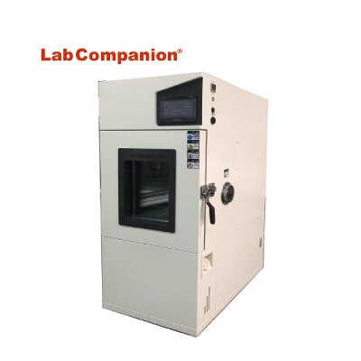
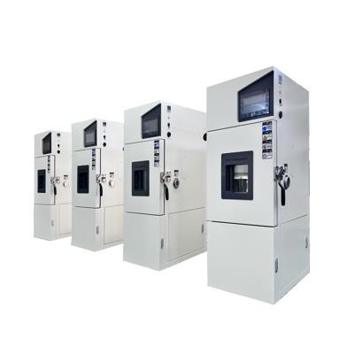
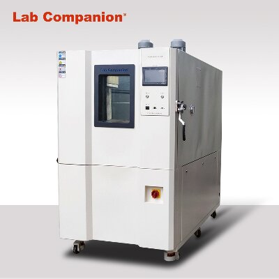
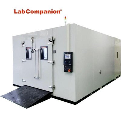
EC-85MHPM-W, Tanque de temperatura y humedad constante correspondiente a carga alta (800 L)ProyectoTipoSerieMHPM-WFunciónModo de temperatura y humedad.El camino de la pelota mojadarango de temperatura-40 ~ + 100 ℃Rango de humedad20 ~ 98% HR(Según la anafase 3 ítems)Cambios de temperatura y humedad.± 0,3 ℃ / ±2,5% HRDistribución de temperatura y humedad.± 0,5 ℃ / ±5,0% HRLa temperatura baja el tiempo.+20 ~ -40 ℃75 añosTiempo de aumento de temperatura-40 ~ + 100 ℃50 añosSe analizó el volumen interno del útero.800LMétodo de pulgadas de la sala de prueba (ancho, profundidad y altura)1000 mm × 800 mm × 1000 mmMétodo de pulgadas del producto (ancho, profundidad y altura)1400 mm × 1190 mm × 1795 mmhacer el materialEquipo externoPanel de control de la sala de pruebassala de maquinasPlaca de acero fría, placa de acero fría beige(Tabla de colores 2.5Y8/2)AdentroPlaca de acero inoxidable (SUS304,2B pulida)Material de calor rotoPrueba de úteroresina sintética dura―PuertaAlgodón espuma de resina sintética dura, algodón de vidrioProyectoTipoSerieMHPM-WEliminación de enfriamiento, dispositivo húmedo Método de enfriamiento Modo de contracción de sección mecánica. Medio de enfriamientoR404AUno mismo puede encoger la máquina.Producción (número de empleados)1,5kW(1)Refrigeración y deshumidificadorTipo de disipador de calor mixto multicanalel condensadorDisipador de radiador mixto multicanal (refrigeración por aire)calorificadorFormaCalentador de aleación de níquel-cromo resistente al calorVolumen3,5kW humidificador Formageneración de vaporVolumen1.8Kw×2SopladorFormaDisipador de radiador mixto multicanal (refrigeración por aire)Capacidad del motor40WUnidad de agua de alimentaciónEl cilindro de suministro de agua Método de suministro de aguaCalidad del aguaAgua pura * Suministro de agua automático("Consulte el suministro automático de agua.")Volumen tipo de gravedad Disco hidratante tipo de gravedad ControladorRango de ajuste de temperatura-42,0 ~ + 102,0 ℃Rango de ajuste de humedad0 ~ 98% HR (temperatura de bulbo seco 10 ~ 85 ℃)Rango de tiempo establecido0 ~ 999 Tiempo de 59 min (tipo de configuración del programa) 0 ~ 20000 Tiempo de 59 min (el tipo de valor)Establecer energía de descomposiciónTemperatura 0,1 ℃, humedad 1% RH durante 1 minIndicar precisiónTemperatura ± 0,8 ℃ (tp.), humedad ± 1% RH (tp.), tiempo ± 100 PPMTipo de vacacionesValor o programaNúmero de etapa20 etapas / 1 programaEl número de procedimientosEl número máximo de programas de fuerza entrante (RAM) es 32 programasEl número máximo de programas ROM internos es de 13 programas.Número de ida y vuelta 98 veces máximo o ilimitadoNúmero de repeticiones de ida y vueltaMáximo 3 pesadosDesplazar el finalPt 100Ω (a 0 ℃), grado (JIS C 1604-1997)Acción de controlAl dividir la acción PIDFunción internaFunción de entrega anticipada, función de espera, función de mantenimiento del valor de configuración, función de protección contra cortes de energía,Función de selección de acción de potencia, función de mantenimiento, función de transporte de ida y vuelta,Función de entrega de tiempo, función de salida de señal de tiempo, función de prevención de sobrecalentamiento y sobreenfriamiento,Función de representación anormal, función de salida de alarma externa, función de representación de paradigma de configuración,Función de selección del tipo de transporte, el tiempo de cálculo representa la función, la función de la lámpara de la lámpara de ranuraProyectoTipoSerieMHPM-WPanel de controlmaquina de equipoPanel de operación LCD (tipo panel de contacto),Representa lámpara (alimentación, transporte, anormal), terminal de fuente de alimentación de prueba, terminal de alarma externa,Terminal de salida de señal horaria, conector del cable de alimentación Dispositivo protector Ciclo frigoríficoDispositivo de protección contra sobrecargas, dispositivo de bloqueo alto.calorificadorDispositivo de protección contra sobrecalentamiento, fusible de temperaturahumidificador Dispositivo de prevención de quemaduras de aire, regulador de nivel de agua de disco humidificadorSopladorDispositivo de protección contra sobrecargaPanel de controlDisyuntor de fugas para fuente de alimentación, fusible (para calentador, humidificador),Fusible (para circuito de operación), dispositivo de protección contra aumento de temperatura (para prueba),Dispositivo de prevención de sobreenfriamiento por aumento de temperatura (material de prueba, en microcomputadora)Subproductos (conjuntos)Receptor de la casa (4), tablero de la casa (2), mecha de bola húmeda (15), manual de operación (1)Productos de equipamientoAdventiciaVidrio de borosilicato duro 800 mm × 800 mm2Orificio para cablesTamaño del orificio 50 mm1El comedero dentro de la lámpara.AC100V 15W Bola blanca caliente2Rueda 4Ajuste horizontal 4Características del electrovirusFuente CA trifásica 380V 50HzCorriente de carga máxima25ACapacidad del disyuntor de fugas para el suministro de energía.50ACorriente sensorial 30mAEspesor de distribución de energía14mm2Manguera aislante de cauchoGrosor del cable de tierra5,5 mm2TuberíaTubo de desagüePT1/2
Consejos de mantenimiento diario para cámaras de prueba de alta y baja temperatura y cámaras de prueba alternadas de alta y baja temperatura1. Cámaras de prueba de alta y baja temperatura. son generalmente relativamente altos y recomendamos colocarlos en un ambiente de temperatura relativamente benigna. Nuestro valor de temperatura de experiencia es de 8 ℃ ~ 23 ℃. Para los laboratorios que no cuenten con esta condición, se deberán equipar aires acondicionados o torres de enfriamiento adecuados.2. Es necesario adherirse a una gestión profesional por parte de personal dedicado. Las unidades con condiciones deben enviar periódicamente personal dedicado a la fábrica del proveedor para capacitación y aprendizaje, con el fin de obtener más experiencia y capacidad profesional en el mantenimiento y reparación de instrumentos Hongzhan.3. Limpie periódicamente el condensador cada 3 meses: para los compresores que utilizan refrigeración por aire, el ventilador del condensador debe inspeccionarse periódicamente y el condensador debe limpiarse y quitarse el polvo para garantizar una buena ventilación y rendimiento de transferencia de calor; Para los compresores que utilizan refrigeración por agua, además de asegurar la presión y temperatura del agua de entrada, también es necesario asegurar el caudal correspondiente. También es necesaria una limpieza y desincrustación periódica del interior del condensador para obtener su rendimiento continuo de transferencia de calor.4. Limpie periódicamente el evaporador: debido a los diferentes niveles de limpieza de las muestras de prueba, se acumularán muchas partículas pequeñas, como polvo, en el evaporador bajo la circulación de aire forzado y deben limpiarse con regularidad.5. Limpieza y equilibrio de las aspas de aire circulante y los ventiladores del condensador: de manera similar a la limpieza de los evaporadores, debido a los diferentes entornos de trabajo de la cámara de prueba, muchas partículas pequeñas, como polvo, pueden acumularse en las aspas de aire circulante y los ventiladores del condensador, y deben limpiarse. regularmente.6. Limpieza del conducto de agua y del humidificador: Si el conducto de agua no es liso y el humidificador se incrusta, es fácil que el humidificador se seque y se queme, lo que puede dañarlo. Por lo tanto, es necesario limpiar periódicamente el conducto de agua y el humidificador.7. Después de cada experimento, ajuste la temperatura cerca de la temperatura ambiente, trabaje durante unos 30 minutos, luego corte la energía y limpie la pared interior del taller.Si es necesario reubicar el equipo, es mejor hacerlo bajo la guía del personal técnico de Hongzhan Company para evitar daños innecesarios o daños al equipo.Cuando el producto no esté en uso durante un largo período de tiempo, se debe encender regularmente cada medio mes y el tiempo de encendido no debe ser inferior a 1 hora.10. Principio de mantenimiento:Debido a que las cámaras de prueba de alta y baja temperatura se componen principalmente de sistemas eléctricos, de refrigeración y mecánicos, una vez que hay un problema con el equipo, se debe realizar una inspección y un análisis exhaustivos de todo el sistema del equipo.En términos generales, el proceso de análisis y juicio puede comenzar con "externo" y luego con "interno", es decir, después de excluir los factores externos, el equipo se puede descomponer sistemáticamente en función del fenómeno de falla. Entonces, el sistema podrá analizarse y juzgarse exhaustivamente. Alternativamente, se puede utilizar el método de razonamiento inverso para encontrar la causa de la falla: primero, verifique si hay un problema con el sistema eléctrico de acuerdo con el diagrama de cableado eléctrico y, finalmente, verifique si hay un problema con el sistema de refrigeración. Antes de comprender la causa de la falla, no es aconsejable desmontar o reemplazar componentes a ciegas para evitar problemas innecesarios.
¡La primera estación de prueba de formación de hielo en un entorno natural en China, construida conjuntamente por la Universidad de Chongqing y la Oficina de Energía Eléctrica de Huaihua, se ha instalado en la montaña Xuefeng!El 16 de enero, se llevó a cabo en Huaihua el seminario de intercambio de tecnología de prueba de cubierta de hielo aislante "Estación de prueba de cubierta de hielo natural Xuefengshan", organizado conjuntamente por la Universidad de Chongqing y el Instituto de Diseño de Energía Eléctrica Hunan Huaihua. Expertos en líneas de transmisión y distribución y tecnología de aislamiento de reconocidas universidades de todo el país, así como expertos en electricidad de la compañía japonesa NGK, se reunieron para celebrar la finalización oficial de la única estación de prueba de capa de hielo natural del mundo y la primera de China en Huaihua. Hunan, y para discutir cuestiones de investigación de seguimiento.En la reunión, el profesor Jiang Xingliang, supervisor doctoral de la Universidad de Chongqing, expresó en primer lugar su agradecimiento a la Oficina de Energía Eléctrica de Huaihua y a varias unidades del sistema eléctrico por su firme apoyo y asistencia en el diseño básico y la construcción de la base experimental. Los expertos asistentes escucharon el informe del profesor asociado Zhang Zhijin sobre la construcción de la estación de prueba de la capa de hielo natural de Xuefengshan y la prueba de la capa de hielo de 2009, compartieron los resultados de la observación y la investigación del hielo en la base de pruebas a lo largo de 2009 y llevaron a cabo debates e investigaciones en profundidad. sobre los problemas existentes. Después de la reunión, los expertos también fueron a la "Estación de prueba de la capa de hielo natural de Xuefengshan" para realizar una investigación in situ, y los representantes expresaron su afirmación sobre la selección del sitio y la construcción de la estación de prueba.El profesor Jiang Xingliang explicó que desde el desastre del hielo de 2008, para evitar un gran número de desconexiones de líneas, derrumbes de torres y accidentes causados por congelaciones severas, y para mantener el funcionamiento seguro y estable de la red eléctrica, el Ministerio de Ciencia y Tecnología de China ha incluido la tecnología de protección y formación de hielo en la red como uno de los temas de investigación importantes del Plan Nacional Clave de Investigación y Desarrollo Básico (Plan 973). Con el apoyo de proyectos como "Cubierta de hielo, deshielo y mecanismos de fusión de líneas de transmisión" de State Grid Corporation de China, el equipo de investigación del profesor Jiang Xingliang llevó a cabo una investigación exhaustiva de las condiciones típicas de la capa de hielo en China, analizó y comparó la capa de hielo. fenómenos y micrometeorología en Liupanshui, Guizhou, montañas Qinling, Shaanxi, Jingmen, Sichuan y Lushan, Jiangxi. Sobre la base de la representatividad, duración y condiciones de transporte de la capa de hielo, se determinó establecer una "base de prueba de la capa de hielo natural" en Xuefengshan, Hunan. Se creía que las condiciones naturales de Pingshantang en Xuefengshan y la solidez técnica del Instituto de Diseño Huaihua cumplían los requisitos para la construcción de bases de prueba de la capa de hielo natural. Finalmente se determinó la selección del sitio y el socio de cooperación.En 2009, el profesor Jiang Xingliang, el profesor asociado Zhang Zhijin y el Dr. Hu Jianlin, entre otros miembros clave del grupo de investigación, dirigieron a más de diez estudiantes graduados del Departamento de Alto Voltaje y Tecnología de Aislamiento de la Universidad de Chongqing para superar diversas dificultades en trabajo y vida en duras condiciones naturales. Trabajaron junto con el Huaihua Bureau Design Institute para construir una base experimental natural mientras realizaban investigaciones experimentales. En el primer año del experimento, se estudiaron los procesos de formación de hielo, descongelación y deshielo de seis especificaciones típicas de conductores comúnmente utilizados en líneas de transmisión de alto voltaje, voltaje ultra alto y voltaje ultra alto. Se observaron y compararon los procesos de formación de hielo de varios tipos de aisladores. Se investigaron experimentalmente múltiples medidas técnicas para prevenir la formación de hielo en los conductores, como recubrimientos mecánicos e hidrofóbicos, así como recubrimientos para prevenir la formación de hielo en los aisladores y diferencias en las disposiciones de formación de hielo en los aisladores. Se analizaron el proceso de torsión y el mecanismo de formación de hielo en los conductores, y se analizaron los cambios de tensión y los cambios en la carga del viento helado después de la formación de hielo en los conductores. Además, se realizaron pruebas de formación de hielo en CA y CC en entornos naturales. Se acumuló una gran cantidad de datos experimentales clave para superar el problema mundial de la formación de hielo en las redes eléctricas, y se realizaron muchos estudios y exploraciones eficaces.Toshiyuki Nakajima, ingeniero jefe de la división de energía eléctrica de NGK Corporation en Japón, declaró en una entrevista con periodistas durante su inspección de la estación de pruebas de la capa de hielo natural de Xuefengshan que ha estado involucrado en investigaciones sobre la capa de hielo de la red eléctrica en los Estados Unidos durante 10 años. Aunque los expertos internacionales han realizado investigaciones a largo plazo sobre la capa de hielo de la red eléctrica en condiciones de simulación artificial de laboratorio, creen unánimemente que existe un error significativo entre la forma de la capa de hielo en el entorno de simulación artificial y la situación real en el entorno natural. La primera estación de prueba de la capa de hielo natural construida en Xuefengshan promoverá sin duda en gran medida el proceso de investigación de la capa de hielo y los mecanismos de derretimiento de las líneas de transmisión y la capacidad antihielo de las redes eléctricas en China e internacionalmente. Desea que sus homólogos chinos obtengan pronto la base de la capa de hielo en las líneas de transmisión en entornos naturales. Los datos llenan el vacío en la investigación internacional en este campo y superan el desafío de clase mundial del mecanismo de formación de hielo de la red eléctrica y la tecnología antihielo lo antes posible.Zhang Jiwu, presidente del Instituto de Diseño de la Oficina de Energía Eléctrica de Huaihua, afirmó que con el fuerte apoyo del secretario Liang Liqing del Comité del Partido de la Oficina de Energía Eléctrica de Huaihua, se construyó la estación de prueba de la capa de hielo natural de Xuefengshan en cooperación con la Universidad de Chongqing. Por un lado, puede contribuir a la investigación sobre la mejora de la resistencia al hielo de la red eléctrica y reflejar el sentido de responsabilidad social de la empresa; Por otro lado, también puede mejorar su propia fortaleza tecnológica y reputación corporativa a través de la cooperación y el intercambio, mejorar su competitividad externa y lograr una situación en la que todos ganen. Es un modelo de cooperación de "investigación universitaria industrial" entre empresas e instituciones de educación superior. (Shu Daisong y Zhang Deming)Fuente de información: Compañía de energía eléctrica de HunanLab Companion tiene una institución de investigación especializada en el desarrollo de equipos de pruebas ambientales, con laboratorios y métodos de investigación de pruebas ambientales maduros. Ha reunido a un grupo de excelentes talentos y reconocidos expertos en la industria, y un sólido equipo de I+D está liderando la dirección de desarrollo de la tecnología de pruebas ambientales nacionales. En la actualidad, la empresa tiene derechos de propiedad intelectual independientes en equipos de prueba ambiental, equipos de prueba de confiabilidad, cámaras de prueba de alta y baja temperatura, cámaras de prueba de humedad de alta y baja temperatura, cámaras de prueba de temperatura y humedad constantes, cámaras de prueba de cambio rápido de temperatura, frío y calor. cámaras de prueba de choque, tres cámaras de prueba integrales, cámaras de prueba de alta y baja temperatura y baja presión, cámaras de prueba de radiación solar, hornos industriales, cámaras de prueba de choque frío y caliente, cámaras de prueba de temperatura y humedad constantes, cámaras de prueba de detección de estrés ambiental, cámaras de prueba de temperatura y humedad constantes, cámaras de prueba de impacto de temperatura alta y baja, máquinas de prueba de humedad y temperatura constantes, cámaras de prueba de humedad y temperatura constante, cámaras de prueba de radiación solar, cámaras de prueba de humedad de temperatura alta y baja, cámaras de control de temperatura y humedad , Máquinas de prueba de envejecimiento acelerado por UV, máquinas de prueba de intemperismo acelerado por UV, cámaras de prueba sin cita previa, cámaras de prueba ambientales sin cita previa. Sala, laboratorio de alta y baja temperatura, cámara de prueba de control de temperatura y humedad, cámara de prueba de resistencia a la intemperie UV, probador de envejecimiento UV, equipo de prueba del entorno climático y productos personalizados, incluidos temperatura alta, baja y cámaras de prueba de baja presión, cámaras de prueba de ciclos rápidos de temperatura, cámaras de prueba de temperatura y humedad constantes, cámaras de prueba de humedad y temperatura constantes, hornos de precisión, cámaras de prueba de humedad y temperatura constantes programables, máquinas de prueba de humedad y temperatura constantes programables, cámaras de prueba de envejecimiento de lámparas de xenón, alta y Las cámaras de prueba de humedad alterna de baja temperatura, las cámaras de prueba de humedad y temperatura constante, las cámaras de prueba de humedad de temperatura alta y baja y las cámaras de prueba de lluvia de alta velocidad del viento están a la vanguardia de los estándares nacionales e internacionales. Invitamos a clientes nuevos y antiguos a contactarnos para consultas. ¡Estaremos dedicados a servirle!


 Consigue una cotización
 Red IPv6 compatible