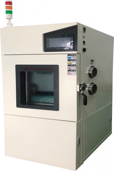
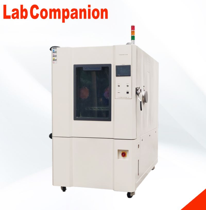
Posición de instalación de iluminación de la cámara de prueba de alta y baja temperaturaSegún las diferentes necesidades de los usuarios, la posición de instalación de la lámpara en el laboratorio de alta y baja temperatura es diferente. La cámara de prueba de temperatura y humedad constantes prueba la resistencia al calor, la resistencia al frío, la resistencia en seco y la resistencia a la humedad de varios materiales. Adecuado para control de calidad en industrias electrónicas, eléctricas, alimentarias, vehiculares, metalúrgicas, químicas, de materiales de construcción y otras. Esta serie de productos es adecuada para productos aeroespaciales, instrumentos electrónicos de información, materiales, productos eléctricos, electrónicos, diversos componentes electrónicos en ambientes de alta y baja temperatura o temperatura y humedad, para probar sus diversos indicadores de rendimiento.El equipo de prueba de temperatura más común en equipos de prueba ambiental y productos relacionados similares son cámara de prueba alternante de alta y baja temperatura, cámara de prueba de temperatura y humedad constante, cámara de prueba alternante de temperatura y humedad alta y baja, etc. Es adecuado para pruebas de confiabilidad de productos industriales a altas y bajas temperaturas. La cámara de prueba de alta y baja temperatura sin cita previa, la cámara de prueba de alta y baja temperatura sin cita previa se utiliza para pruebas térmicas de la industria de defensa nacional, la industria aeroespacial, componentes automáticos, piezas de automóviles, piezas electrónicas y eléctricas, plásticos, industria química, farmacéutica y productos relacionados. Proporciona piezas grandes, productos semiacabados y un gran espacio ambiental para pruebas de temperatura y humedad para productos terminados. Es adecuado para equipos de prueba con gran cantidad y volumen.Algunos están instalados en la cámara interior o en la puerta y otros no están instalados. ¿Cuál es el mejor lugar para instalar bombillas?De hecho, la iluminación de la cámara de pruebas de alta y baja temperatura tiene ventajas y desventajas sin importar dónde se instale.Si la iluminación está instalada en la sala de transmisión, podrá ver claramente el estado de toda la sala de transmisión y observar el producto en cualquier momento.La lámpara se instala en la puerta, y cuando el usuario realiza la prueba doble 85 o la prueba de alta temperatura y alta humedad, no es fácil que la humedad invada la lámpara y la lámpara no es fácil de dañar, lo que puede reducir en gran medida el Tarifa de servicio posventa. Sin embargo, su campo de observación es muy pequeño, sólo puede observar las atracciones cercanas, los clientes observan el producto no es muy conveniente.Si la lámpara se instala en el lado derecho de la cámara interna, se recomienda sellarla completamente para evitar la entrada de humedad y garantizar el funcionamiento estable a largo plazo de la lámpara. Si se instala en una puerta, se recomienda que la ventana de visualización sea trapezoidal, para que pueda tener un campo de visión más amplio.Por supuesto, algunos clientes corporativos optan por no instalar iluminación al comprar cámaras de prueba de alta y baja temperatura para reducir los costos de producción y los costos de gestión posteriores. Sin embargo, los clientes no pueden observar los productos en ningún momento cuando realizan pruebas y no pueden satisfacer las necesidades de diferentes clientes que desean observar los productos.
Cámara de prueba de vacío térmico - Equipo de prueba de simulación terrestre para entornos espacialesUso del producto del equipo de prueba de simulación terrestre del entorno espacial:El equipo de prueba de simulación terrestre en entorno espacial se utiliza para productos militares y aeroespaciales en el entorno terrestre para simular el vacío espacial, el entorno negro frío y la radiación solar, la prueba de vacío térmico y la prueba de balance de calor. El equipo de prueba de simulación terrestre del entorno espacial puede simular el ambiente frío y caliente del espacio vacío, llevar a cabo pruebas de vacío térmico en piezas de prueba y controlar, monitorear y registrar de manera efectiva la temperatura de las piezas de prueba en el espacio vacío, lo que proporciona las condiciones para la prueba de productos aeroespaciales.El equipo de prueba de simulación terrestre del entorno espacial cumple los criterios:Requisitos de prueba de vehículos, etapas superiores y naves espaciales GJB 1027AMétodo de prueba de equilibrio térmico del satélite GJB 1033Método de prueba de equilibrio térmico del satélite QJ 1446AMétodo de prueba de entorno espacial QJ2630.1 para componentes de satélites: prueba de vacío térmicoMétodo de prueba del entorno espacial QJ2630.2 para componentes de satélites: prueba de equilibrio térmicoQJ2630.3 Método de prueba en entorno espacial para componentes de satélites: prueba de descarga al vacíoGB 150-1998 Recipiente a presión de aceroGB/T 3164-2007 Símbolos gráficos para dibujos de sistemas de tecnología de vacíoBrida de vacío GB/T 6070-2007GB 50054-1995 Especificación de diseño para distribución de bajo voltaje.GB 50316-2008 Especificación para el diseño de tuberías metálicas industriales.Parámetros técnicos del equipo de prueba de simulación terrestre del entorno espacial:Tamaño del tanque de vacío (m): Phi 1X1.5 Phi 2x2.5 in 3x3.5Vacío máximo (pa): ≤5x10⁻⁵Vacío de trabajo (pa): ≤1.0x10⁻³Modo de refrigeración: modo refrigerante, modo medio de trabajo compuesto y modo de refrigeración con nitrógeno líquidoDisipador de calor + placa fría: Disipador de calor + jaula calefactora Disipador de calor de nitrógeno líquido + jaula calefactoraRango de temperatura: -70 ℃ ~ +130 ℃ -150 ℃ ~ +150 ℃ -173 ℃ ~ +170 ℃Estabilidad de temperatura: ≤1℃/h ≤1℃/h ≤1℃/hUniformidad de temperatura: ≤±2.0℃ ≤±3.0℃ ≤±5.0℃Precisión del control de temperatura: ±1 ℃ ±1 ℃ ±1 ℃Velocidad de elevación y enfriamiento: >1℃/minTasa de fuga del sistema de vacío:
Soluciones de pruebas ambientales para el transporte de vehículos AutopartesLa confiabilidad de los productos de autopartes para el transporte de vehículos es muy importante, lo que determina directamente la seguridad, confiabilidad y comodidad de operación del vehículo.IndustriaObjeto de pruebaUsarTecnologíaSoluciónindustria del automóvilElectrónica automotrizInspeccionarPrueba de alta y baja temperatura.Cámara de prueba de alta y baja temperatura (y humedad)EvaluarPrueba de alta y baja temperatura.Cámara de prueba de alta temperaturaPrueba de potencia de condensaciónCámara de prueba de cambio rápido de temperatura (y humedad) Prueba característicaCámara de prueba de cambio rápido de temperatura (y humedad) Batería de cocheInspeccionarPrueba de carga y descargaCámara de prueba de alta y baja temperatura (y humedad)EvaluarPrueba característicaCámara de prueba de cambio rápido de temperatura (y humedad) Dispositivo de seguridad para caminarInspeccionarEnvejecimiento del sustratoCámara de prueba de alta y baja temperatura (y humedad)EvaluarPrueba característicaCámara de prueba de alta temperaturaProtección de los ocupantes (airbag)InspeccionarCribado de producto terminadoCámara de prueba de cambio rápido de temperatura (y humedad)Sistema de guía de conducción de automóvilesInspeccionarCribado de producto terminadoCámara de prueba de alta y baja temperatura (y humedad)Cámara de prueba de cambio rápido de temperatura (y humedad) Sistema de operación de vehículos ETCInspeccionarPrueba de alta y baja temperatura.Cámara de prueba de alta y baja temperatura (y humedad)Cámara de prueba de alta temperaturaEvaluarPrueba característicaCámara de prueba de cambio rápido de temperatura (y humedad) Otras asociaciones de automoción (semiconductores de potencia) Colocar a alta temperaturaCámara de prueba de alta temperatura
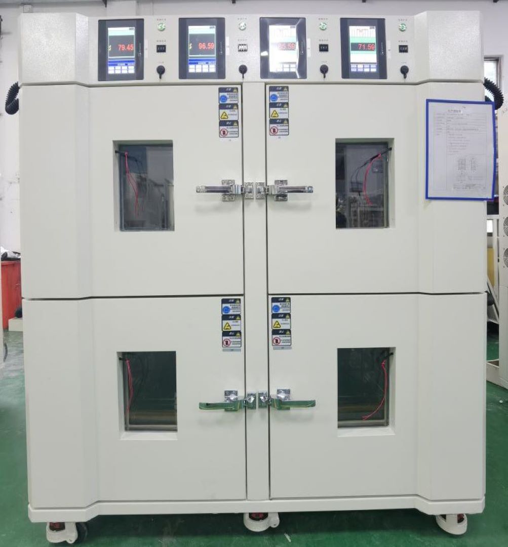
Cámara de prueba especial de batería
Introducción a la cámara de prueba de la cámara de prueba especial de batería:
Prueba ambiental de alta y baja temperatura (húmeda y caliente) para celdas de batería de litio, módulos y prueba de paquete de batería de energía de vehículo eléctrico; También se utiliza para pruebas ambientales de alta y baja temperatura (húmeda y caliente) de celdas y módulos de baterías de litio relacionados con la industria del almacenamiento de energía.
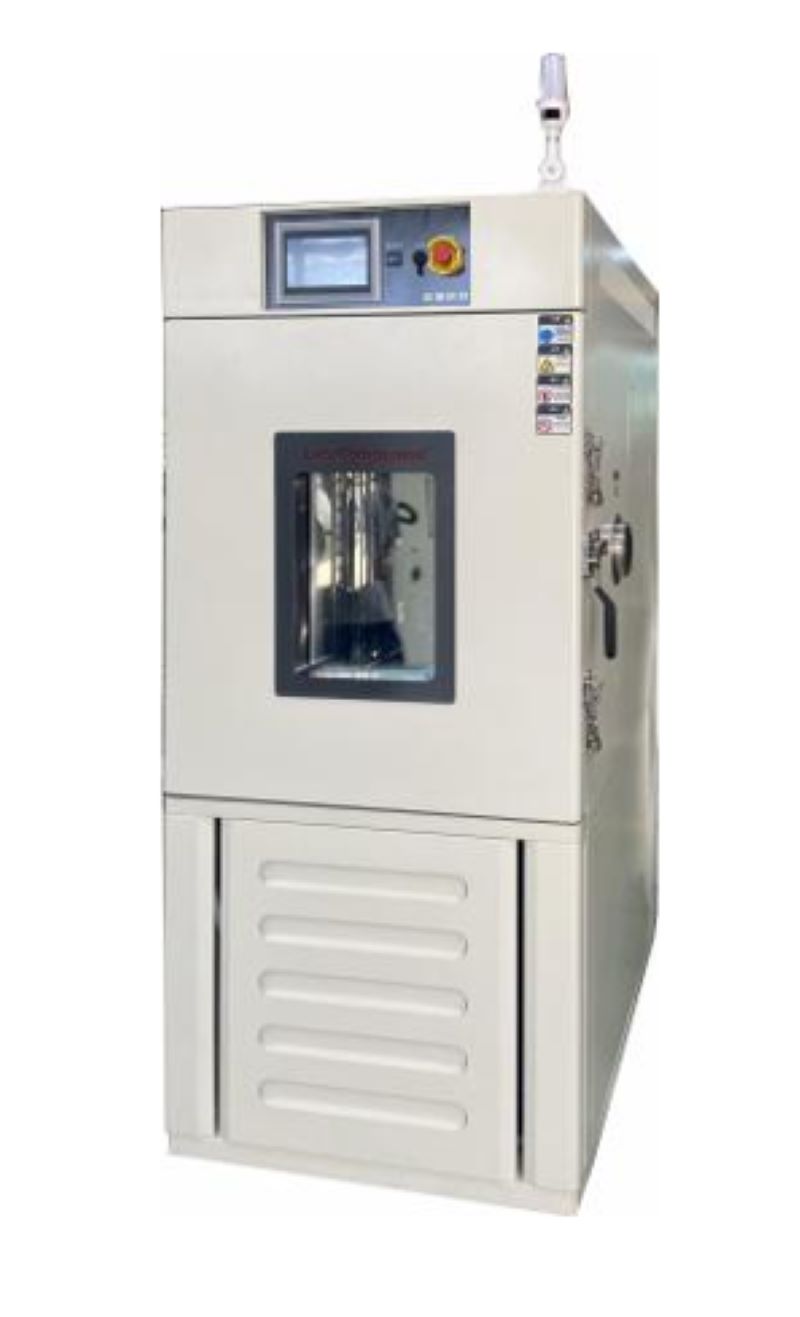
Parámetros principales de la cámara de prueba especial de batería:
Tamaño del estudio: 0,3 m ~ 1,5 m³ (se pueden personalizar otros tamaños)
Rango de temperatura: -40 ℃ ~ +150 ℃
Rango de humedad: 20% ~ 98%
Velocidad de calentamiento: 1 ℃ -5 ℃/min (todo el proceso)
Velocidad de enfriamiento: 1 ℃ -5 ℃/min (todo el proceso)
Fluctuación de temperatura: ±0,5
Uniformidad de temperatura: 2 ℃
Desviación de temperatura: ±2℃
Desviación de humedad: +2 ~ -3% (> 75% RH), ± 5% (≤ 75% RH)
Pruebas de quemadoPruebas de quemado es el proceso mediante el cual un sistema detecta fallas tempranas en componentes semiconductores (mortalidad infantil), aumentando así la confiabilidad de un componente semiconductor. Normalmente, las pruebas de funcionamiento se realizan en dispositivos electrónicos, como diodos láser, con un sistema de funcionamiento automático de diodos láser de equipo de prueba que hace funcionar el componente durante un período prolongado para detectar problemas.Un sistema de precintado utilizará tecnología de vanguardia para probar el componente y proporcionar control preciso de la temperatura, potencia y mediciones ópticas (si es necesario) para garantizar la precisión y confiabilidad requeridas para las aplicaciones de fabricación, evaluación de ingeniería y I+D.Se pueden realizar pruebas de precalentamiento para garantizar que un dispositivo o sistema funcione correctamente antes de salir de la planta de fabricación o para confirmar que los nuevos semiconductores del laboratorio de I+D cumplan con los requisitos operativos diseñados.Es mejor realizar un rodaje a nivel de componente cuando el costo de probar y reemplazar piezas es más bajo. El quemado de una placa o de un conjunto es difícil porque los diferentes componentes tienen límites diferentes.Es importante señalar que la prueba de quemado generalmente se utiliza para filtrar dispositivos que fallan durante la “etapa de mortalidad infantil” (inicio de la curva de la bañera) y no toma en cuenta la “vida útil” o el desgaste (final de la curva de la bañera). curva): aquí es donde entran en juego las pruebas de confiabilidad.El desgaste es el final natural de la vida útil de un componente o sistema relacionado con el uso continuo como resultado de la interacción de los materiales con el medio ambiente. Este régimen de fallas es de particular interés al indicar la vida útil del producto. Es posible describir matemáticamente el desgaste permitiendo el concepto de confiabilidad y, por lo tanto, la predicción de la vida útil.¿Qué causa que los componentes fallen durante el período de precalentamiento?La causa principal de las fallas detectadas durante las pruebas de precalentamiento se puede identificar como fallas dieléctricas, fallas de conductores, fallas de metalización, electromigración, etc. Estas fallas están latentes y se manifiestan aleatoriamente en fallas del dispositivo durante el ciclo de vida del dispositivo. Con las pruebas de quemado, un equipo de prueba automático (ATE) estresará el dispositivo, acelerando estas fallas latentes para que se manifiesten como fallas y las descarte durante la etapa de mortalidad infantil.Las pruebas de quemado detectan fallas que generalmente se deben a imperfecciones en los procesos de fabricación y empaque, que se están volviendo más comunes con la creciente complejidad de los circuitos y el escalado tecnológico agresivo.Parámetros de prueba de quemadoLa especificación de una prueba de funcionamiento varía según el dispositivo y el estándar de prueba (estándares militares o de telecomunicaciones). Por lo general, requiere la prueba eléctrica y térmica de un producto, utilizando un ciclo eléctrico operativo esperado (condición operativa extrema), generalmente durante un período de 48 a 168 horas. La temperatura térmica de la cámara de prueba de quemado puede oscilar entre 25 °C y 140 °C.El quemado se aplica a los productos a medida que se fabrican, para detectar fallas tempranas causadas por fallas en la práctica de fabricación.Burn In Fundamentalmente realiza lo siguiente:Estrés + Condiciones Extremas + Prolongar Tiempo = Aceleración de la “Vida Normal/Útil”Tipos de pruebas de quemadoBurn-in dinámico: el dispositivo está expuesto a altos voltajes y temperaturas extremas mientras está sujeto a diversos estímulos de entrada.Un sistema de precalentamiento aplica varios estímulos eléctricos a cada dispositivo mientras el dispositivo está expuesto a temperaturas y voltajes extremos. La ventaja del calentamiento dinámico es su capacidad de estresar más circuitos internos, provocando que se produzcan mecanismos de falla adicionales. Sin embargo, el desgaste dinámico es limitado porque no puede simular completamente lo que experimentaría el dispositivo durante el uso real, por lo que es posible que no se estresen todos los nodos del circuito.Quemado estático: el dispositivo bajo prueba (DUT) se somete a tensión a una temperatura elevada y constante durante un período prolongado de tiempo.Un sistema de precalentamiento aplica voltajes o corrientes y temperaturas extremas a cada dispositivo sin operar ni ejercitar el dispositivo. Las ventajas del burn-in estático son su bajo coste y su simplicidad.¿Cómo se realiza una prueba de quemado?El dispositivo semiconductor se coloca en placas de precintado especiales (BiB) mientras que la prueba se ejecuta dentro de una cámara de precintado especial (BIC).Conozca más sobre la cámara de quemado (haga clic aquí)
Equipos de prueba de baja presión y alta y baja temperatura y dispositivo de descompresión rápidaCámara de prueba de baja presión y alta temperatura.:(1). Principales indicadores técnicos1. Tamaño del estudio: 1000D×1000W×1000H mm, el tamaño interno es de aproximadamente 1000L2. Tamaño externo: aproximadamente 3400D×1400W×2010H mm, excluyendo el controlador, el orificio de prueba y otras partes prominentes.3. Rango de temperatura: -70 ℃ ~ +150 ℃4. Fluctuación de temperatura: ≤±0,5 ℃, presión normal, sin carga5. Desviación de temperatura: ±2℃, presión normal, sin carga6. Uniformidad de temperatura: ≤2℃, presión atmosférica, sin carga7. Velocidad de calentamiento: +20℃→+150℃≤60min8. Velocidad de enfriamiento: +20℃→-65℃≤60min9. Rango de humedad: Humedad 20% ~ 98% RH (rango de temperatura +20℃ ~ +85℃)10. Desviación de humedad: ≤+ 2-3%RH (> 75%RH), ≤±5%RH(≤75%RH), bajo presión normal y condiciones sin carga.11. Rango de presión: presión normal ~ 0,5 kPa12. Tasa de reducción de presión: presión normal ~ 1,0 kPa≤30min13. Tasa de recuperación de presión: ≤10,0 kPa/min14. Desviación de presión: presión normal ~ 40kPa:≤±2kPa, 40KPa ~ 4kPa:≤±5%kPa, por debajo de 4kPa:≤± 0,1kPa15. Velocidad del viento: ajuste de conversión de frecuencia16. Potencia: alrededor de 50kW17. Ruido: ≤75dB (A), a 1 metro del frente de la cámara y a 1,2 metros del suelo.18. Peso: 1900Kg(2). Dispositivo de descompresión rápida (opcional)Para cumplir con los requisitos de una despresurización rápida, se procesa una cámara de despresurización rápida independiente. La cámara de despresurización rápida se compone de un conjunto de carcasa, un conjunto de presión, un conjunto de puerta, una interfaz y un marco móvil. Antes de una descompresión rápida, el usuario debe conectar una tubería externa.1. Tamaño del estudio: 400 mm de profundidad x 500 mm de ancho x 600 mm de largo; El material de la pared interna se procesa con 3.0 SUS304/2B y se utiliza un tubo cuadrado de 5 mm como refuerzo de presión.2. Dimensión externa: 530 mm de profundidad × 700 mm de ancho × 880 mm de largo, el material de la pared externa está hecho de una placa de acero laminada en frío de 1,2 mm, la superficie está rociada de blanco (consistente con el color de la cámara);3. Hay un puerto para sensor de presión reservado en la parte superior del contenedor. El puerto del sensor de control está ubicado en la parte trasera del contenedor para facilitar la ruta del dispositivo de cierre rápido.4. Para la comodidad de mover el dispositivo de inversión rápida. Instale cuatro ruedas elevadoras debajo del marco; El marco móvil está soldado con acero ordinario y rociado sobre la superficie.5. Proceso de descompresión rápida: para mejorar la velocidad de bombeo de la cámara de despresurización rápida, primero se bombea la cámara de prueba a aproximadamente 1 kPa y se abre la válvula eléctrica que conecta el equipo de la cámara de prueba y el dispositivo de reducción rápida para realizar la función de reducción rápida. , y la válvula se cierra cuando alcanza 18,8 kPa. La presión constante en la cámara de alivio rápido se puede lograr mediante bombeo auxiliar (válvula de admisión).(3). Estándares de implementación del producto.1. GB/T2423.1-2008 Prueba A: Prueba de baja temperatura2. GB/T2423.2-2008 Prueba B: Prueba de baja temperatura3. Cabina de prueba GB/T 2423.3-2006: prueba de temperatura y humedad constantes4. Prueba GB/T 2423.4-2008 Db: prueba alterna de temperatura y humedad5. GB/T2423.21-2008 Prueba M: Método de prueba de baja presión6. Prueba GB/T2423.25-2008 Z/AM: Prueba integral de baja temperatura/baja presión7. GB/T2423.26-2008 Prueba Z/BM: prueba integral de alta temperatura/baja presión8. Requisitos generales para GJB150.1-20099. Prueba de baja presión (altitud) GJB150.2A-200910. Prueba de alta temperatura GJB150.3A-200911. Prueba de baja temperatura GJB150.4A-200912. Prueba de temperatura-altura GJB150.6-8613. GJB150.19-86 Temperatura - humedad - prueba de altura14. Prueba rápida de descompresión DO16F15. Condiciones técnicas de la cámara de prueba de temperatura y humedad GB/T 10586-200616. Condiciones técnicas de la cámara de prueba de baja presión y alta temperatura GB/T 10590-200617. Norma técnica de la cámara de prueba de alta y baja temperatura GB/T 10592-200818. GB/T 5170.1-2008 Reglas generales para métodos de inspección de equipos de prueba ambientales para la industria eléctrica y electrónica19. GB/T 5170.2-2008 Productos eléctricos y electrónicos Equipo de prueba ambiental Método de prueba Equipo de prueba de temperatura y humedad20. GB/T 5170.5-2008 Productos eléctricos y electrónicos Equipo de prueba ambiental Método de prueba Equipo de prueba de temperatura y humedadGB/T 5170.10-2008 Productos eléctricos y electrónicos Equipo de prueba ambiental Método de prueba Equipo de prueba de alta temperatura y baja presión
Tablero de grabación para pruebas de confiabilidadLos equipos semiconductores que prueban y detectan fallas tempranas durante la etapa de “mortalidad infantil” se colocan en una placa conocida como “placa de quemado”. En una placa precintada, hay varios enchufes para colocar el dispositivo semiconductor (es decir, diodo láser o fotodiodo). La cantidad de dispositivos que se colocan en una placa puede consistir en lotes bajos de 64 a más de 1000 dispositivos al mismo tiempo.Estas placas de precintado luego se insertan en el horno de precintado que puede controlarse mediante un ATE (equipo de prueba automático) que suministra los voltajes obligatorios hacia las muestras mientras mantiene la temperatura deseada del horno. La polarización eléctrica aplicada puede ser estática o dinámica.Por lo general, los componentes semiconductores (es decir, diodos láser) se empujan más allá de lo que tendrán que atravesar en un uso normal. Esto garantiza que el fabricante pueda estar seguro de que tiene un dispositivo de fotodiodo o diodo láser robusto y que el componente puede cumplir con los estándares de confiabilidad y calificación. Opciones de materiales para tableros quemados:IS410IS410 es un sistema preimpregnado y laminado de epoxi FR-4 de alto rendimiento diseñado para soportar los requisitos de la industria de placas de circuito impreso para niveles más altos de confiabilidad y la tendencia a utilizar soldadura sin plomo.370 horasLos laminados y preimpregnados 370HR se fabrican utilizando un sistema patentado de resina epoxi multifuncional Tg FR-4 de alto rendimiento a 180 °C que está diseñado para aplicaciones de tablero de cableado impreso (PWB) multicapa donde se requiere el máximo rendimiento térmico y confiabilidad.Epoxi BTEl epoxi BT se elige ampliamente por sus excelentes propiedades térmicas, mecánicas y eléctricas. Este laminado es adecuado para el montaje de PCB sin plomo. Se utiliza principalmente para aplicaciones de placas multicapa. Presenta una excelente electromigración, resistencia de aislamiento y alta resistencia térmica. También mantiene la fuerza de unión a altas temperaturas.polimidaEl epoxi BT se elige ampliamente por sus excelentes propiedades térmicas, mecánicas y eléctricas. Este laminado es adecuado para el montaje de PCB sin plomo. Se utiliza principalmente para aplicaciones de placas multicapa. Presenta una excelente electromigración, resistencia de aislamiento y alta resistencia térmica. También mantiene la fuerza de unión a altas temperaturas.Nelco 4000-13La serie Nelco® N4000-13 es un sistema de resina epoxi mejorado diseñado para proporcionar excelentes propiedades térmicas y de alta velocidad de señal/baja pérdida de señal. N4000-13 SI® es excelente para aplicaciones que requieren una integridad de señal óptima y un control de impedancia preciso, manteniendo al mismo tiempo una alta confiabilidad a través de CAF 2 y resistencia térmica. Grosor del tablero quemado:0,062” – 0,125” (1,57 mm – 3,17 mm) Aplicaciones de tableros grabados:Durante el proceso de quemado se aplican temperaturas extremas que a menudo oscilan entre 125 °C y 250 °C o incluso 300 °C, por lo que los materiales utilizados deben ser extremadamente duraderos. IS410 se utiliza para aplicaciones de tableros quemados de hasta 155 °C y, normalmente, una poliimida para aplicaciones de hasta 250 °C. Los tableros quemados se pueden utilizar en condiciones de pruebas ambientales tales como:HAST (estrés de temperatura y humedad altamente acelerado)LTOL (vida operativa a baja temperatura)HTOL (vida operativa a alta temperatura) Requisitos de diseño del tablero grabado:Una de las consideraciones más importantes es seleccionar la mayor confiabilidad y calidad posibles para la placa Burn in y el zócalo de prueba. No desea que su placa o enchufe Burn in falle antes que el dispositivo bajo prueba. Por lo tanto, todos los componentes y conectores activos/pasivos deben cumplir con los requisitos de alta temperatura, y todos los materiales y componentes deben cumplir con los requisitos de alta temperatura y envejecimiento.
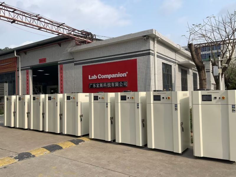
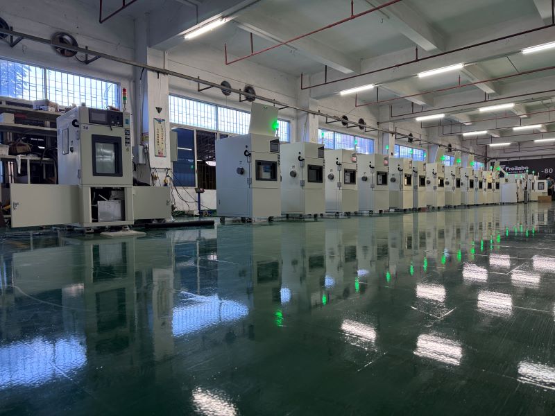
¿Qué son las pruebas ambientales?Los dispositivos electrónicos y productos industriales de los que dependemos todos los días se ven afectados por el medio ambiente de muchas maneras, incluida la temperatura, la humedad, la presión, la luz, las ondas electromagnéticas y las vibraciones. Las pruebas ambientales analizan y evalúan el impacto de estos factores ambientales en el producto para determinar su durabilidad y confiabilidad.Compañero de laboratorio de Guangdong LTD., tiene un capital registrado de 10 millones de yuanes y 3 plantas de fabricación de I+D en Dongguan, Kunshan y Chongqing. Lab Companion se ha especializado en tecnología de equipos de prueba de alta y baja temperatura durante 19 años, operando de acuerdo con cuatro sistemas ISO9001, ISO14001, ISO 45001, ISO27001, estableciendo centros de servicio de ventas y mantenimiento en Shanghai, Wuhan, Chengdu, Chongqing, Xi 'an y Hong Kong. Trabajamos en estrecha colaboración con la Organización Internacional de Metrología Legal, la Academia China de Ciencias, State Grid, China Southern Power Grid, la Universidad de Tsinghua, la Universidad de Pekín, la Universidad de Ciencia y Tecnología de Hong Kong y otras instituciones de investigación.Los principales productos de Lab Companion incluyen cámara de prueba de alta y baja temperatura, cámara de prueba de temperatura y humedad constantes, cámara de prueba de ciclos rápidos de temperatura, cámara de prueba de choque térmico, cámara de prueba de alta y baja temperatura y baja presión, vibración de la cámara integral, horno industrial, horno de vacío, horno de nitrógeno, etc., que proporciona experimentos de alta calidad equipos para universidades, institutos de investigación, salud médica, inspección y cuarentena, monitoreo ambiental, alimentos y medicamentos, fabricación de automóviles, petroquímicos, productos de caucho y plástico, semiconductores IC, fabricación de TI y otros campos.
Verificación vibratoria de funcionalidad (VVF)En la vibración generada durante el transporte, las cajas de carga son susceptibles a presiones dinámicas complejas y la respuesta resonante generada es violenta, lo que puede provocar fallas en el embalaje o en el producto. Identificar la frecuencia crítica y el tipo de presión sobre el paquete minimizará esta falla. La prueba de vibraciones es la evaluación de la resistencia a las vibraciones de componentes, componentes y máquinas completas en el entorno previsto de transporte, instalación y uso.Los modos de vibración comunes se pueden dividir en vibración sinusoidal y vibración aleatoria. La vibración sinusoidal es un método de prueba de uso frecuente en el laboratorio, que simula principalmente la vibración generada por la rotación, pulsación y oscilación, así como el análisis de la frecuencia de resonancia y la verificación de la residencia del punto de resonancia de la estructura del producto. Se divide en vibración de frecuencia de barrido y vibración de frecuencia fija, y su gravedad depende del rango de frecuencia, el valor de amplitud y la duración de la prueba. La vibración aleatoria se utiliza para simular la evaluación general de la resistencia sísmica estructural del producto y el entorno de envío en el estado empaquetado, y la gravedad depende del rango de frecuencia, GRMS, duración de la prueba y orientación axial.La vibración no solo puede aflojar los componentes de la lámpara, provocando un desplazamiento relativo interno, lo que resulta en desoldadura, contacto deficiente, rendimiento laboral deficiente, sino que también puede hacer que los componentes produzcan ruido, desgaste, fallas físicas e incluso fatiga de los componentes.Con este fin, Lab Companion lanzó un negocio profesional de "prueba de vibración de lámpara LED" para simular la vibración o choque mecánico que puede ocurrir en el entorno real de transporte, instalación y uso de la lámpara, evaluar la resistencia a la vibración de la lámpara LED y la estabilidad. de sus indicadores de desempeño relacionados, y encontrar el eslabón débil que puede causar daño o falla. Mejore la confiabilidad general de los productos LED y mejore el estado de falla de la industria debido al transporte u otros impactos mecánicos.Clientes de servicio: fábrica de iluminación LED, agentes de iluminación, distribuidores de iluminación, empresas de decoración.Método de prueba:1, el embalaje de muestra de la lámpara LED colocado en el banco de pruebas de vibración;2, la velocidad de vibración del probador de vibraciones se establece en 300 RPM, la amplitud se establece en 2,54 cm, inicia el medidor de vibraciones;3, la lámpara de acuerdo con el método anterior en las tres direcciones superior e inferior, izquierda y derecha, delantera y trasera, respectivamente, se prueba durante 30 minutos.Evaluación de resultados: Después de la prueba de vibración, no pueden producirse caídas de piezas de la lámpara, daños estructurales, iluminación ni otros fenómenos anormales.
Prueba ambiental de confiabilidad de temperatura y humedad constante doble 85 (THB)Primero, prueba de alta temperatura y humedad.WHTOL (vida útil en húmedo a alta temperatura) es una prueba de aceleración de estrés ambiental común, generalmente 85 ℃ y 85 % de humedad relativa, que generalmente se lleva a cabo de acuerdo con la norma IEC 60068-2-67-2019. Las condiciones de prueba se muestran en la tabla.En segundo lugar, el principio de prueba.La "prueba doble 85" es una de las pruebas ambientales de confiabilidad, utilizada principalmente para cajas de temperatura y humedad constantes, es decir, la temperatura de la caja se establece en 85 ℃, la humedad relativa se establece en condiciones de 85 % RH, para acelerar la envejecimiento del producto de prueba. Aunque el proceso de prueba es simple, la prueba es un método importante para evaluar muchas características del producto de prueba, por lo que se ha convertido en una condición de prueba ambiental de confiabilidad indispensable en diversas industrias.Después de envejecer el producto en condiciones de 85 ℃/85 % RH, compare los cambios de rendimiento del producto antes y después del envejecimiento, como los parámetros de rendimiento fotoeléctrico de la lámpara, las propiedades mecánicas del material, el índice amarillo, etc. cuanto menor sea la diferencia, mejor, para probar la resistencia al calor y la humedad del producto.El producto puede tener fallas térmicas cuando funciona en un ambiente continuo de alta temperatura, y algunos dispositivos sensibles a la humedad fallarán en un ambiente de alta humedad. La prueba dual 85 puede probar el estrés térmico generado por el producto bajo alta humedad y su capacidad para resistir la penetración de humedad a largo plazo. Por ejemplo, las frecuentes fallas de varios productos durante el período de clima húmedo en el sur se deben principalmente a la mala resistencia de los productos a la temperatura y la humedad.3. Factores experimentalesEn la industria de la iluminación LED, muchos fabricantes han utilizado los resultados de las pruebas dobles 85 como un medio importante para juzgar la calidad de las lámparas. Varias posibles razones por las que las lámparas LED no superan la prueba dual 85 son:1. Fuente de alimentación de la lámpara: mala resistencia al calor de la carcasa, peligro de cortocircuito en el circuito, falla del mecanismo de protección, etc.2. Estructura de la lámpara: diseño irrazonable del cuerpo de disipación de calor, problemas de instalación, los materiales no son resistentes a altas temperaturas.3. Fuente de luz de la lámpara: mala resistencia a la humedad, envejecimiento del adhesivo de embalaje, resistencia a altas temperaturas.Si se encuentra en un entorno de uso especial, como la temperatura ambiente de trabajo es severa, es necesario probar su resistencia a altas y bajas temperaturas, el método de prueba puede referirse al proyecto de prueba de altas y bajas temperaturas.4. Servir a los clientes01. Grupo de clientesFábrica de iluminación LED, planta de energía LED, fábrica de embalaje LED02. Medios de detecciónCámara de prueba de temperatura y humedad constantes03. Estándares de referenciaPruebas de temperatura y humedad constantes para productos eléctricos y electrónicos - Pruebas ambientales - Parte 2: Métodos de prueba - Cabina de prueba: Prueba de humedad y temperatura constante GB/T 2423.3-2006.04. Contenido del servicio4.1 Consulte la norma, realice una prueba doble 85 en el producto y proporcione el informe de resultados de la prueba de terceros.4.2 Proporcionar el análisis y plan de mejora del producto mediante el doble test 85.
Prueba de confiabilidadCertificación de prueba AEC-Q102 Calor húmedo fijo con ciclos de humedad (FMG), método de prueba de confiabilidad de la lámpara LED (GB/T 33721-2017), prueba de detección de componentes Prueba CAF de amoníaco, prueba de corrosión cíclica de grado retardante de llama (CCT), prueba de choque mecánico, Prueba de olla de alta presión (PCT), Prueba de estrés altamente acelerada (HAST), Prueba de temperatura y humedad alta y baja (THB), Prueba de sulfuro de hidrógeno (H2S), Tanque de líquido prueba de choque térmico (TMSK), prueba de grado de componente sensible a la humedad (MSL), detección para uso de alta confiabilidad Prueba de sofoco + detección de barrido acústico para uso de alta confiabilidad (MSL+SAT), esquema de prueba de confiabilidad de luminarias LED, prueba de vibración (VVF), Prueba de ciclo de temperatura/choque térmico (TC/TS), prueba de tinta roja LED, prueba de envejecimiento UV, prueba de antivulcanización de fuente de luz LED, prueba ambiental de confiabilidad de temperatura y humedad constante Doble 85 (THB), prueba de niebla salina.
Cámara de prueba de ciclos de temperatura rápida Lab CompanionIntroducción de Lab CompanionCon más de 20 años de experiencia, Compañero de laboratorio es un fabricante de cámaras ambientales de clase mundial y un destacado proveedor de sistemas y equipos de prueba llave en mano. Todas nuestras cámaras se basan en la reputación de Lab Companion de larga vida útil y confiabilidad excepcional. Con un alcance de diseño, fabricación y servicio, Lab Companion ha establecido un sistema de gestión de calidad que cumple con la Norma Internacional del Sistema de Calidad ISO 9001:2008. El programa de calibración de equipos de Lab Companion está acreditado según la norma internacional ISO 17025 y la norma nacional estadounidense ANSI/NCSL-Z-540-1 por A2LA. A2LA es miembro de pleno derecho y signatario de la Cooperación Internacional de Acreditación de Laboratorios (ILAC), la Acreditación de Laboratorios de Asia Pacífico (APLAC) y la Cooperación Europea para la Acreditación (EA). Las cámaras de pruebas ambientales de la serie SE de Lab Companion ofrecen un sistema de flujo de aire significativamente mejorado, que proporciona mejores gradientes y mejores tasas de cambio de temperatura del producto. Estas cámaras utilizan el programador/controlador 8800 insignia de Thermotron, que cuenta con una pantalla plana de 12,1” de alta resolución con interfaz de usuario táctil, capacidades ampliadas para realizar gráficos, registrar datos, editar, acceder a ayuda en pantalla y almacenamiento de datos en el disco duro a largo plazo.No solo ofrecemos productos de la más alta calidad, sino que también brindamos soporte continuo diseñado para mantenerlo en funcionamiento mucho después de la venta inicial. Brindamos servicio local directo de fábrica con un extenso inventario de las piezas que pueda necesitar. ActuaciónRango de temperatura: -70°C a +180°CRendimiento: Con una carga de aluminio de 23 kg (IEC60068-3-5), la velocidad de aumento de +85 °C a -40 °C es de 15 ℃/min; la velocidad de enfriamiento de -40 °C a +85 °C también es de 15 ℃/min.Control de temperatura: ± 1°C Temperaturas de bulbo seco desde el punto de control después de la estabilización en el sensor de controlEl rendimiento se basa en una condición ambiental de 75 °F (23,9 °C) y 50 % de humedad relativa.Rendimiento de refrigeración/calefacción basado en la medición en el sensor de control en la corriente de aire de suministroestructuraInteriorAcero inoxidable no magnético Serie 300 con alto contenido de níquelCosturas internas soldadas con heliarco para sellado hermético del liner.Esquinas y uniones diseñadas para permitir la expansión y contracción bajo las temperaturas extremas encontradas.Drenaje de condensado ubicado en el piso del liner y debajo del pleno de acondicionamientoLa base de la cámara está completamente soldada.Aislamiento de fibra de vidrio que no se asienta “Ultra-Lite”Un estante interior ajustable de acero inoxidable es estándarExteriorChapa de acero tratada moldeadaSe proporcionan cubiertas de acceso metálicas para facilitar la apertura de las puertas a los componentes eléctricos.Acabado de laca a base de agua, seca al aire, rociada sobre una superficie limpia e imprimada.Puertas de acceso con bisagras fáciles de levantar para dar servicio al sistema de refrigeraciónUn puerto de acceso de 12,5 cm de diámetro con soldadura interior y tapón aislante extraíble montado en accesorios de pared del lado derecho en puerta con bisagras para fácil acceso.CaracterísticasLa operación de la cámara muestra claramente información útil sobre el tiempo de ejecuciónGraphing Screen ofrece capacidades ampliadas, programación e informes mejoradosEl estado del sistema muestra parámetros cruciales del sistema de refrigeraciónLa entrada de programa facilita la carga, visualización y edición de perfiles.Los asistentes de configuración de pasos rápidos facilitan la entrada al perfilTablas de refrigeración emergentes para una referencia prácticaTherm-Alarm® proporciona protección de alarma de temperatura excesiva o insuficienteLa pantalla de registro de actividad proporciona un historial completo del equipoEl servidor web permite el acceso a Internet al equipo a través de EthernetEl teclado emergente fácil de usar hace que la entrada de datos sea rápida y sencillaIncluye:- Cuatro puertos USB: dos externos y dos internos- Ethernet-RS-232Especificaciones técnicas1-4 canales programables independientementePrecisión de medición: 0,25 % del intervalo típicoEscala de temperatura seleccionable °C o °FPantalla táctil de panel plano en color de 12,1” (30 cm)Resolución: 0,1°C, 0,1%RH, 0,01 para otras aplicaciones linealesReloj en tiempo real incluidoFrecuencia de muestreo: variable de proceso muestreada cada 0,1 segundosBanda Proporcional: Programable 1.0° a 300°Método de control: DigitalIntervalos: IlimitadoResolución de intervalo: 1 segundo a 99 horas, 59 minutos con resolución de 1 segundo-RS-232- Más de 10 años de almacenamiento de datos- Control de temperatura del producto- Tablero de retransmisión de eventosModos de funcionamiento: Automático o ManualAlmacenamiento del programa: ilimitadoBucles de programa:- Hasta 64 bucles por programaLos bucles se pueden repetir hasta 9999 veces.- Se permiten hasta 64 bucles anidados por


 Consigue una cotización
 Red IPv6 compatible