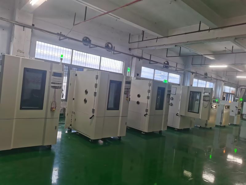
In industrial testing and scientific research, Lab Companion’s environmental test chambers are essential for product reliability verification, widely applied in electronics, automotive, aerospace, home appliances and other sectors. Both chambers focus on temperature range simulation and are easily confused in selection, yet differ sharply in core functions and application scenarios. This guide clarifies their key similarities, differences and scientific selection logic for optimal matching.
I. Key Commonalities
Both are artificial environmental simulation devices for evaluating product stability in extreme temperatures, providing data support for R&D, mass production testing and quality control, and complying with GB, IEC, ISO and other international standards.
1. Overlapping temperature range: -70℃~150℃ for high and low temperature chambers, -40℃~150℃ for constant temperature and humidity chambers, covering most industrial basic temperature test needs.
2. Unified operation & precision: Equipped with intelligent control systems (supporting parameter preset, curve programming, data export); temperature control accuracy ±0.5℃, fluctuation ≤±1℃.
II. Core Differences
The fundamental distinction is the presence of a humidity control module, which defines functional boundaries, application scenarios, structure, cost and O&M:
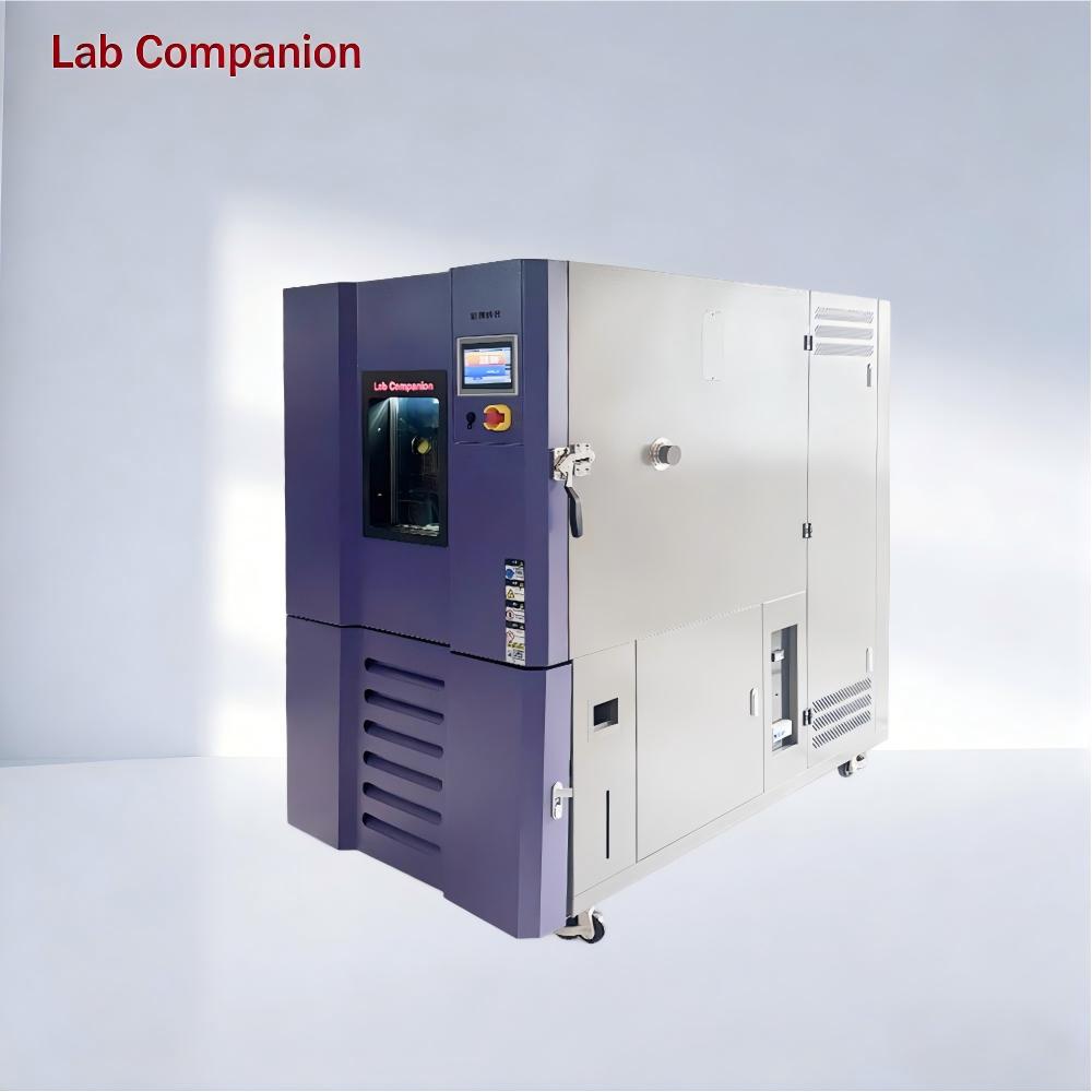
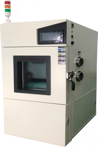
High and Low Temperature Test Chamber
1. Core Function: Only temperature regulation (heating/cooling/constant temperature), no humidity control module
2. Typical Scenarios: Temperature-only tests, e.g., high/low temperature cycle of electronic components, temperature impact of auto parts
3. Structure: Simplified configuration (heater, refrigeration system); better thermal insulation, smaller footprint for the same specification
4. Cost & O&M: Lower procurement cost; simple routine maintenance for refrigeration/heating system only, low energy consumption
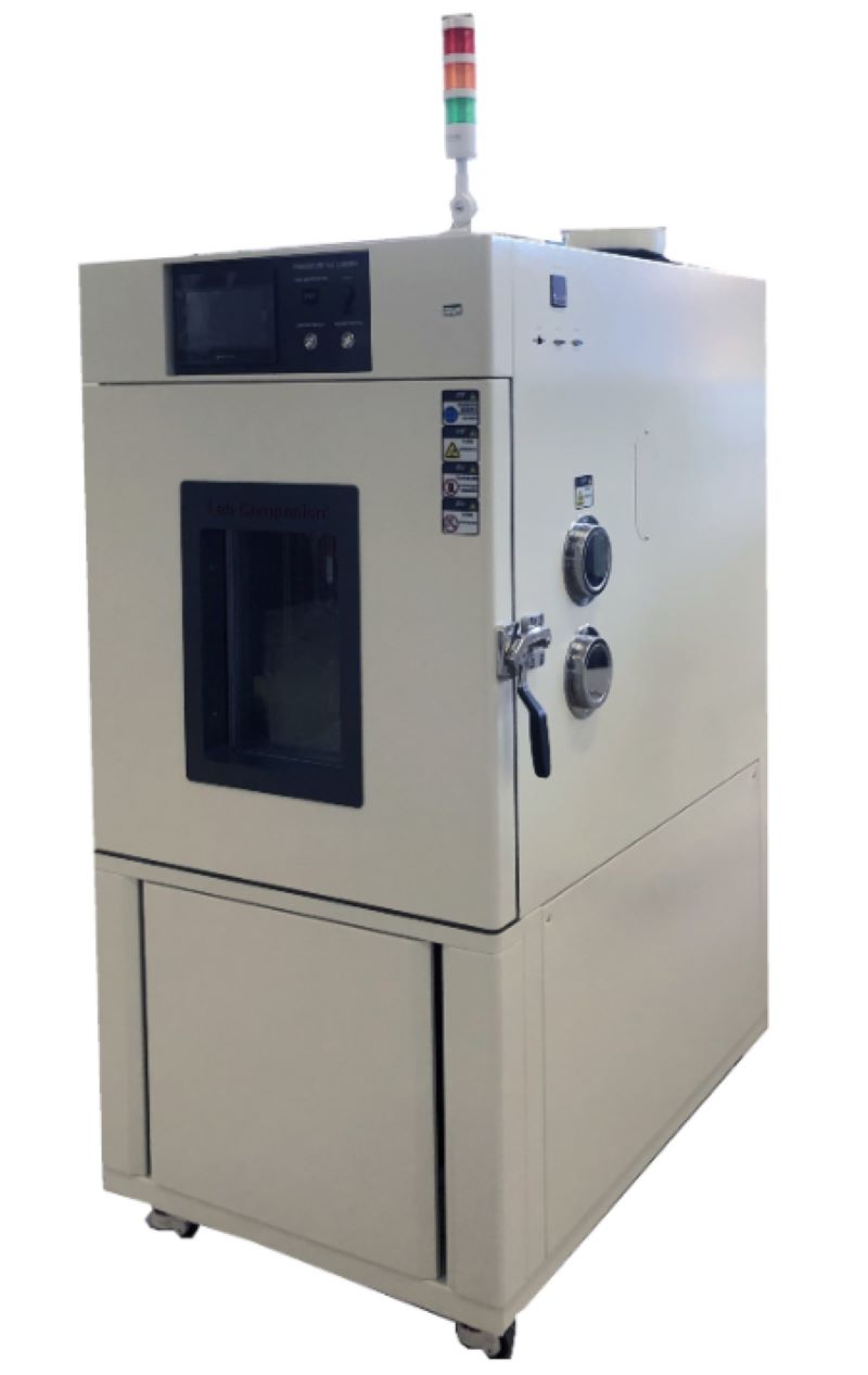
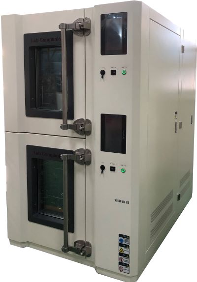
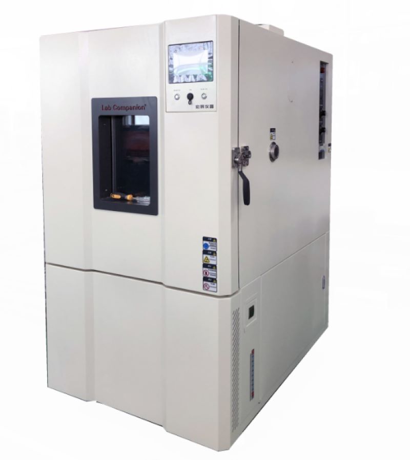
Constant Temperature and Humidity Test Chamber
1. Core Function: Dual regulation of temperature and humidity; humidity range 40%~95%RH (20%~98%RH for premium models), accuracy ±2%RH
2. Typical Scenarios: Temperature-humidity synergy tests, e.g., damp heat aging of electronics, humidity storage of medical devices, damp heat operation of home appliances
3. Structure: Complex configuration (humidification tank, dehumidifier, high-seal box); additional components for professional humidity control
4. Cost & O&M: 15%~30% higher procurement cost by specification; regular O&M for humidity parts (tank cleaning, sensor calibration), relatively higher energy consumption.
III. Selection Guide
Adhere to demand-oriented matching and balance cost performance with the following core principles:
1. Choose High and Low Temperature Test Chamber if: Only temperature change testing is needed, humidity has no impact on results, budget is limited, or laboratory space is narrow (high cost performance, easy O&M)
2. Choose Constant Temperature and Humidity Test Chamber if: Temperature-humidity synergy simulation is required, compliance with industry humidity test standards is needed, or testing moisture/corrosion-prone samples (focus on humidity parameters and reserve O&M budget)
IV. Conclusion
Lab Companion’s two test chambers both deliver stable temperature regulation for diverse industrial needs, with core differences rooted in the humidity control module. The high and low temperature chamber is ideal for basic temperature-only tests with its specialized function and cost efficiency; the constant temperature and humidity chamber excels in complex environmental simulation with its dual temperature-humidity regulation capability.
Abandon the misconception of "more functions = better". Optimal selection relies on integrating core test needs, budget, O&M capacity and laboratory space, to achieve the best balance between test effectiveness and long-term use cost. The two chambers complement each other, forming the core competitiveness of Lab Companion’s environmental test chamber series.
La clave para crear un entorno de pruebas seguro para el laboratorio cámara de prueba de alta y baja temperatura Consiste en garantizar la seguridad personal, la seguridad del equipo, la seguridad de la pieza de prueba y la precisión de los datos.1. Consideraciones de seguridad personalAntes de abrir la puerta de la cámara de alta temperatura para extraer la muestra, es necesario usar correctamente el equipo de protección resistente a altas y bajas temperaturas. Al realizar operaciones que puedan causar salpicaduras o fugas de gases extremadamente calientes o fríos, se recomienda usar mascarilla o gafas protectoras.La cámara de prueba debe instalarse en un laboratorio bien ventilado y evitar operar en espacios reducidos. Las pruebas a alta temperatura pueden liberar sustancias volátiles de la pieza de prueba. Una buena ventilación puede prevenir la acumulación de gases nocivos.Asegúrese de que las especificaciones del cable de alimentación cumplan con los requisitos del equipo y que el cable de tierra esté conectado de forma segura. Es fundamental que no toque los enchufes, interruptores ni muestras con las manos mojadas para evitar descargas eléctricas. 2. Instale el equipo correctamenteSe debe mantener la distancia mínima de seguridad especificada por el fabricante (normalmente de al menos 50 a 100 centímetros) en la parte posterior, superior y lateral del equipo para garantizar el correcto funcionamiento del condensador, el compresor y otros sistemas de disipación de calor. Una ventilación deficiente puede provocar el sobrecalentamiento del equipo, una disminución del rendimiento e incluso un incendio.Se recomienda proporcionar una línea de alimentación dedicada para la cámara de prueba para evitar compartir el mismo circuito con otros equipos de alta potencia (como acondicionadores de aire e instrumentos grandes), que pueden causar fluctuaciones de voltaje o disparos.Se recomienda que la temperatura ambiente para el funcionamiento del equipo esté entre 5 °C y 30 °C. Una temperatura ambiente excesivamente alta aumentará significativamente la carga del compresor, lo que provocará una disminución de la eficiencia de refrigeración y fallos de funcionamiento. Tenga en cuenta que el equipo no debe instalarse bajo la luz solar directa, cerca de fuentes de calor ni en lugares con fuertes vibraciones. 3. Garantizar la validez y repetibilidad de las pruebasLas muestras deben colocarse en el centro de la cámara de trabajo dentro de la caja. Debe haber suficiente espacio entre ellas y con la pared de la caja (generalmente se recomienda más de 50 mm) para garantizar una circulación de aire fluida dentro de la caja y una temperatura uniforme y estable.Después de realizar pruebas de alta temperatura y alta humedad (como en una cámara de temperatura y humedad constantes), si se requieren pruebas de baja temperatura, se deben realizar operaciones de deshumidificación para evitar la formación excesiva de hielo dentro de la cámara, lo que podría afectar el rendimiento del equipo.Está estrictamente prohibido probar sustancias inflamables, explosivas, altamente corrosivas y altamente volátiles, excepto en cámaras de prueba a prueba de explosiones diseñadas específicamente para este fin. Está estrictamente prohibido colocar mercancías peligrosas como alcohol y gasolina en cámaras comunes de alta y baja temperatura. 4. Especificaciones de operación de seguridad y procedimientos de emergenciaAntes de usar el aparato, compruebe que la puerta de la caja esté bien sellada y que el bloqueo funcione correctamente. Compruebe que la caja esté limpia y libre de objetos extraños. Confirme que la curva de temperatura (programa) sea correcta.Durante el período de prueba, es necesario verificar periódicamente si el estado de funcionamiento del equipo es normal y si hay ruidos o alarmas anormales.Normas de manipulación y colocación de muestras: Use correctamente guantes para altas y bajas temperaturas. Tras abrir la puerta, incline ligeramente el cuerpo hacia un lado para evitar que la ola de calor le dé en la cara. Retire la muestra con rapidez y cuidado y colóquela en un lugar seguro.Respuesta ante emergencias: Familiarícese con la ubicación del botón de parada de emergencia del equipo o cómo cortar rápidamente el suministro eléctrico principal en caso de emergencia. Se deben tener cerca extintores de dióxido de carbono (aptos para incendios eléctricos) en lugar de extintores de agua o espuma.
Al operar una cámara de prueba con temperatura y humedad constantes, es importante estar atento a posibles problemas durante el proceso y garantizar un funcionamiento correcto. Un manejo inadecuado puede provocar fácilmente fallos en el equipo. Sin embargo, con el tiempo, es inevitable que se produzcan algunas fallas. En este artículo, analizaremos varias fallas comunes y sus soluciones.Fallo: Si la temperatura no alcanza el valor establecido durante la prueba de alta temperatura, el primer paso es revisar el sistema eléctrico y solucionar los problemas de cada componente. Si la temperatura en la cámara de prueba de temperatura y humedad constantes aumenta demasiado lentamente, revise el sistema de circulación de aire para asegurar que la compuerta de ajuste funcione correctamente. Si la temperatura aumenta demasiado rápido, ajuste la configuración del PID. Si la temperatura aumenta demasiado rápido y activa la protección contra sobretemperatura, el controlador podría estar defectuoso; en este caso, reemplace el panel de control o el relé de estado sólido. Fallo: Si la cámara de prueba de temperatura y humedad constantes no cumple con los requisitos de la prueba de baja temperatura, investigue si la temperatura desciende muy lentamente o si se estabiliza en un punto determinado antes de volver a subir. Si la temperatura desciende muy lentamente, compruebe si la cámara se secó antes de la prueba de baja temperatura para mantener la sequedad. Asegúrese de que las muestras no estén demasiado apretadas para evitar una circulación de aire inadecuada. Tras descartar estos problemas, considere si el sistema de refrigeración está fallando; en tal caso, solicite una reparación profesional al fabricante. Fallo: Si la cámara de prueba de temperatura y humedad constantes presenta un fallo durante su funcionamiento y el panel de control muestra un mensaje de fallo y una alarma sonora, el operador puede consultar la sección de resolución de problemas del manual del usuario del equipo para identificar el tipo de fallo. El personal de mantenimiento profesional deberá realizar las reparaciones necesarias para garantizar el correcto desarrollo de la prueba. Otros equipos experimentales ambientales tendrán otras condiciones de uso, que deberán abordarse según la situación actual.
1. Descripción general del equipoLa cámara de pruebas de humedad y temperatura, también conocida como aparato de simulación ambiental, es un instrumento de precisión que requiere un estricto cumplimiento de los protocolos operativos. Como dispositivo eléctrico de Clase II que cumple con las normas de seguridad IEC 61010-1, su fiabilidad (estabilidad de temperatura de ±0,5 °C), precisión (precisión de humedad relativa de ±2 %) y estabilidad operativa son fundamentales para obtener resultados de pruebas que cumplan con la norma ISO/IEC 17025.2. Protocolos de seguridad previos a la operación2.1 Requisitos eléctricos Alimentación: 220 V CA ±10 %, 50/60 Hz con conexión a tierra independiente (resistencia de tierra ≤4 Ω) Instalar un circuito de parada de emergencia y protección contra sobrecorriente (se recomienda el 125 % de la corriente nominal) Implementar RCD (dispositivo de corriente residual) con corriente de disparo ≤30 mA2.2 Especificaciones de instalación Requisitos de autorización: Trasero: ≥500 mm Lateral: ≥300 mm Vertical: ≥800 mm Condiciones ambientales: Temperatura: 15-35°C Humedad: ≤85 % HR (sin condensación) Presión atmosférica: 86-106 kPa 3. Restricciones operativas3.1 Entornos prohibidos Atmósferas explosivas (Zona ATEX 0/20 prohibida) Ambientes corrosivos (concentración de HCl >1 ppm) Áreas con alto contenido de partículas (PM2,5 >150 μg/m³)Campos electromagnéticos fuertes (>3 V/m a 10 kHz-30 MHz)4. Procedimientos de puesta en servicio4.1 Lista de verificación previa al inicio Verificar la integridad de la cámara (deformación estructural ≤0,2 mm/m) Confirmar la validez de la calibración del sensor PT100 (trazable al NIST) Verificar los niveles de refrigerante (R404A ≥85% de la carga nominal) Validar la pendiente del sistema de drenaje (pendiente ≥3°)5. Directrices operativas5.1 Configuración de parámetros Rango de temperatura: -70 °C a +150 °C (gradiente ≤3 °C/min) Rango de humedad: 20 % HR a 98 % HR (se requiere monitoreo del punto de rocío >85 % HR) Pasos del programa: ≤120 segmentos con control de rampa y saturación 5.2 Enclavamientos de seguridad Apagado por apertura de puerta (activación en 0,5 s) Protección contra sobretemperatura (sensores redundantes duales) Detección de falla del sensor de humedad (activación del modo de secado automático)6. Protocolo de mantenimiento6.1 Mantenimiento diario Limpieza del serpentín del condensador (aire comprimido 0,3-0,5 MPa) Comprobación de la resistividad del agua (≥1 MΩ·cm) Inspección del sello de la puerta (tasa de fuga ≤0,5 % vol/h) 6.2 Mantenimiento periódico Análisis del aceite del compresor (cada 2.000 horas) Prueba de presión del circuito refrigerante (anual) Ciclo de calibración: Temperatura: ±0,3 °C (anual) Humedad: ±1,5 % HR (semestral)7. Matriz de respuesta a fallosPrioridad de síntomasPrioridadAcción inmediataRespuesta técnicaCalentamiento incontroladoP1Activar parada de emergenciaCompruebe el funcionamiento del SSR (Vf
Para lograr las condiciones de prueba deseadas en una cámara de prueba de temperatura y humedad constante, es inevitable realizar operaciones de humidificación y deshumidificación. Este artículo analiza los diversos métodos comúnmente utilizados en las cámaras de prueba de temperatura y humedad constantes de LabCompanión, destacando sus respectivas ventajas, desventajas y condiciones recomendadas para su uso.La humedad se puede expresar de muchas maneras. Para el equipo de prueba, la humedad relativa es el concepto más utilizado. La humedad relativa se define como la relación de la presión parcial del vapor de agua en el aire a la presión de vapor de saturación del agua a la misma temperatura, expresada como porcentaje.A partir de las propiedades de la presión de saturación de vapor de agua, se sabe que la presión de saturación del vapor de agua es únicamente una función de la temperatura y es independiente de la presión de aire en la que existe el vapor de agua. A través de una extensa organización de experimentación y datos, se ha establecido la relación entre la presión de saturación de vapor de agua y la temperatura. Entre estos, la ecuación de Goff-Gratch se adopta ampliamente en ingeniería y metrología y actualmente es utilizada por los departamentos meteorológicos para compilar tablas de referencia de humedad.Proceso de humidificación La humidificación esencialmente implica aumentar la presión parcial del vapor de agua. El primer método de humidificación fue rociar agua sobre las paredes de la cámara, controlando la temperatura del agua para regular la presión de saturación de la superficie. El agua en las paredes de la cámara forma una gran superficie, a través del cual el vapor de agua se difunde en la cámara, aumentando la humedad relativa dentro. Este método surgió en la década de 1950. En ese momento, el control de la humedad se logró principalmente utilizando medidores de conductividad de contacto de mercurio para una regulación simple de encendido-apagado. Sin embargo, este método era poco adecuado para controlar la temperatura de grandes tanques de agua propensos a retrasos, lo que resultó en largos procesos de transición que no podían satisfacer las demandas de pruebas de humedad alterna que requieren una humidificación rápida. Más importante aún, la pulverización de agua sobre las paredes de la cámara inevitablemente condujo a gotas de agua que cayeron sobre las muestras de prueba, causando diversos grados de contaminación. Además, este método planteaba ciertos requisitos para el drenaje dentro de la cámara. Este método pronto fue reemplazado por humidificación de vapor y humidificación de sartén de agua poco profunda. Sin embargo, todavía tiene algunas ventajas. Aunque el proceso de transición de control es largo, las fluctuaciones de humedad son mínimas una vez que el sistema se estabiliza, lo que lo hace adecuado para pruebas de humedad constantes. Además, durante el proceso de humidificación, el vapor de agua no se sobrecalienta, evitando así la adición de calor adicional al sistema. Además, cuando la temperatura del agua de pulverización se controla para que sea más baja que la temperatura de prueba requerida, el agua de pulverización puede actuar como un deshumidificador. Desarrollo de métodos de humidificación Con la evolución de las pruebas de humedad desde la humedad constante hasta la humedad alterna, surgió la necesidad de capacidades de respuesta de humidificación más rápidas. La humidificación en aerosol ya no podría satisfacer estas demandas, lo que lleva a la adopción generalizada y el desarrollo de la humidificación de vapor y los métodos de humidificación de sartén de aguas poco profundas. Humidificación de vapor La humidificación de vapor implica inyectar vapor directamente en la cámara de prueba. Este método ofrece tiempos de respuesta rápidos y control preciso sobre los niveles de humedad, lo que lo hace ideal para alternar las pruebas de humedad. Sin embargo, requiere una fuente de vapor confiable y puede introducir calor adicional en el sistema, lo que puede necesitar ser compensado por pruebas sensibles a la temperatura. Humidificación de sartén de agua poco profunda La humidificación de la sartén de agua poco profunda utiliza una sartén con calefacción para evaporar el agua en la cámara. Este método proporciona un nivel de humedad estable y consistente y es relativamente simple de implementar. Sin embargo, puede tener tiempos de respuesta más lentos en comparación con la humidificación de vapor y requiere un mantenimiento regular para evitar la escala y la contaminación. Proceso de deshumidificación La deshumidificación es el proceso de reducir la presión parcial del vapor de agua en la cámara. Esto se puede lograr mediante métodos de enfriamiento, adsorción o condensación. La deshumidificación de enfriamiento implica reducir la temperatura de la cámara para condensar el vapor de agua, que luego se elimina. La deshumidificación de adsorción utiliza desecantes para absorber la humedad del aire, mientras que la deshumidificación de la condensación se basa en las bobinas de enfriamiento para condensar y eliminar el vapor de agua. Conclusión En resumen, la elección de los métodos de humidificación y deshumidificación en las cámaras de prueba de temperatura y humedad constantes depende de los requisitos específicos de las pruebas que se realizan. Si bien los métodos más antiguos como la humidificación en aerosol tienen sus ventajas, las técnicas modernas, como la humidificación de vapor y la humidificación de la sartén de agua poco profunda, ofrecen un mayor control y tiempos de respuesta más rápidos, lo que las hace más adecuadas para las necesidades de pruebas avanzadas. Comprender los principios y las compensaciones de cada método es crucial para optimizar el rendimiento de la cámara de prueba y garantizar resultados precisos y confiables.
Configuración y mantenimiento de la cámara de prueba de temperatura y humedad constantesCámara de prueba de temperatura y humedad constantes Es un equipo de prueba relativamente preciso. Para garantizar la finalización sin problemas de cada proceso de prueba, la fuente de alimentación del equipo conectado debe ser estable en alrededor de 380 V para garantizar que el compresor no sufra daños. Además, debe garantizar la seguridad personal del personal que recibe la energía, así que comprenda los métodos de operación específicos antes de realizar el cableado.La cámara de prueba de temperatura y humedad constante ajusta o reemplaza la fuente de alimentación conectada. Después de comprobar que el voltaje de la fuente de alimentación a conectar es correcto, conecte el terminal neutro al terminal neutro de la cámara de distribución. Asegúrese de que la línea neutra esté conectada; de lo contrario, puede provocar que el equipo de la cámara de prueba de temperatura y humedad constantes no funcione normalmente o queme componentes eléctricos.Después de confirmar que el cable neutro está conectado, conecte el cable de 3 ∮ a los tres terminales debajo del interruptor principal de la cámara de distribución en la cámara de prueba de temperatura y humedad constantes y apriete los tornillos. Necesitamos conectar el cable de tierra, que se conecta de la misma manera que otros cables de alimentación, y directamente al terminal de tierra de la cámara de distribución. En el proceso de conexión de cada cable de alimentación, todos deben asegurarse de que los diferentes colores del cable de alimentación puedan identificarse correctamente para evitar errores de conexión y pruebas normales.Mantenimiento de la cámara de prueba de temperatura y humedad constante:1. Limpie el sistema de circulación de agua: limpie el filtro de agua, reemplace el filtro, verifique el funcionamiento de la bomba, incluido el funcionamiento del interruptor de flujo de agua, ajuste el flujo de circulación de agua y pruebe el funcionamiento.2. Verifique todo el cableado eléctrico y los componentes eléctricos para garantizar un funcionamiento confiable y un buen contacto.3. Reemplace el filtro de aire fresco.4, Limpieza del sistema de refrigeración: reemplace el aceite de refrigeración, limpie el filtro de aceite.5. Verifique las partes vulnerables del sistema de refrigeración: verifique el estado de sellado del compresor y las piezas de conexión, y reemplace todos los filtros.6, Inspección de fugas del sistema de refrigeración: verifique que todas las piezas de conexión del sistema de refrigeración y las piezas de conexión de la placa de la válvula tengan fugas y estén apretadas.7. Según las condiciones de trabajo para complementar el refrigerante: verifique si es necesario complementar el refrigerante del sistema para garantizar una capacidad de enfriamiento efectiva.8, Operación integral del sistema: verifique si los componentes operativos están en buenas condiciones.
Método de mantenimiento de la cámara de prueba de alta y baja temperaturaHay tres tipos comunes de cámara de prueba de alta y baja temperatura controladores: falla de software, falla del sistema y falla de hardware.1, falla del software: La falla del software se refiere principalmente a la falla del controlador de la cámara de prueba de alta y baja temperatura, incluidos los parámetros internos, el control IS del punto de control y la señal de salida de encendido y apagado de la válvula solenoide.2, falla del sistema: La falla del sistema se refiere a los problemas de diseño iniciales del sistema de refrigeración, incluida la fuga de refrigerante causada por la cámara de prueba de alta y baja temperatura que no se enfría, y la fuga de refrigerante a menudo se debe al transporte y a la fluctuación de funcionamiento de la cámara de prueba de alta y baja temperatura o a la refrigeración. El proceso de soldadura de tuberías de cobre no está bien y se deben a otras razones.3, falla de hardware: La falla del hardware puede provocar que el compresor, la válvula solenoide y otros componentes de refrigeración no enfríen.Luego, el usuario puede escuchar y tocar para comprender aproximadamente cuál es el daño de la cámara de prueba de alta y baja temperatura del hardware; si se trata de una falla del compresor, el sonido del compresor será anormal o no funcionará, no arranca o la temperatura del compresor en sí es mucho más alta. de lo habitual, y la falla de la válvula solenoide y otros componentes de refrigeración los usuarios no son demasiado buenos para dominar.Además, el daño del controlador y el daño de las partes electrónicas del sistema de refrigeración de control también pueden causar el fenómeno de falta de enfriamiento y falta de enfriamiento de la cámara de prueba de alta y baja temperatura.Principio científico de calentamiento y enfriamiento de cámaras de prueba de alta y baja temperatura:La cámara de prueba de alta y baja temperatura tiene las funciones de calentamiento, enfriamiento, humidificación y deshumidificación, y puede detectar la resistencia a altas temperaturas, bajas temperaturas y humedad del producto. ¿Cómo se controla la temperatura en la cámara de prueba de alta y baja temperatura?El dispositivo de calentamiento es el vínculo clave para controlar si la cámara de prueba de alta y baja temperatura se calienta. El controlador envía voltaje al relé cuando recibe la instrucción de calentamiento. La cámara de prueba de alta y baja temperatura requiere aproximadamente 3-12 voltios de corriente continua agregada al relé de estado sólido. El extremo de CA de la cámara de prueba de alta y baja temperatura es equivalente a una conexión de cable y el contactor también se dibuja al mismo tiempo. Calentar la cámara de prueba de temperatura y humedad constantes.El enfriamiento es una parte importante de la cámara de prueba de alta y baja temperatura, que afecta directamente la determinación de la temperatura alta y baja y el rendimiento, incluido el compresor, el condensador, el dispositivo de estrangulación y el evaporador, cuatro componentes principales; el compresor es el corazón del sistema de refrigeración. Inhala gas de baja temperatura y baja presión, en gas de alta temperatura y alta presión, a través de la condensación en un líquido para liberar calor, a través del ventilador para eliminar el calor, por lo tanto, la cámara de prueba es la razón del aire caliente y luego baja presión del líquido a través estrangulamiento, y luego se convierte en gas de baja temperatura y baja presión a través del evaporador de regreso al compresor, el refrigerante en el evaporador absorbe el calor de la cámara de alta y baja temperatura para completar el proceso de gasificación y absorber el calor, para lograr el propósito de la refrigeración. , para completar el proceso de enfriamiento de la cámara de prueba de alta y baja temperatura.Procedimiento de prueba de velocidad de enfriamiento y temperatura de la cámara de alta y baja temperatura:En el rango ajustable de temperatura de la cámara de prueba, se seleccionó la temperatura nominal más baja como temperatura de enfriamiento más baja y la temperatura nominal más alta se seleccionó como temperatura de calentamiento más alta.Abra la fuente de frío, de modo que la cámara de prueba desde la temperatura ambiente hasta la temperatura de enfriamiento más baja, estable durante al menos 3 horas, aumente a la temperatura de calentamiento más alta, estable durante al menos 3 horas y luego a la temperatura de enfriamiento más baja, durante el calentamiento. y enfriando, registrar una vez por minuto, hasta el final del proceso de prueba.El principio de calentamiento y enfriamiento de la cámara de prueba de alta y baja temperatura es así, la realización de su función se completa mediante la configuración del sistema de control, la comprensión del principio de calentamiento y enfriamiento, en el uso de la cámara de prueba de alta y baja temperatura debe ser más práctico.
Composición de los componentes eléctricos de la cámara de prueba de alta y baja temperatura.
Las partes principales del prueba de alta y baja temperatura cámara son unidades de refrigeración, condensadores, evaporadores y controladores. Las partes principales juegan un papel clave, por lo que todos prestan especial atención a las materias primas de sus partes principales. Sin embargo, la mayoría de ellos ignoran sus piezas auxiliares en este momento, o sienten que no vale la pena destacar el papel de las piezas auxiliares. Pocas personas quieren contar las piezas específicas, por lo que no está claro qué componentes electrónicos específicos se utilizan por completo en la cámara de prueba de temperatura y humedad constantes.
1, unidad de refrigeración:
Se utilizan para controlar el funcionamiento de la unidad de refrigeración, para realizar el ciclo de refrigeración, y los hay monofásicos y trifásicos.
2, motor del ventilador:
Se utiliza para controlar el cuerpo de vapor de circulación del ventilador, la conducción de calor del intercambiador de calor y hay interiores y exteriores.
3, equipo calentador eléctrico:
Se utiliza para calentar la calidad del aire interior, puntos tubulares y floculantes.
4, temporizador:
Se utiliza para el arranque de sincronización del sistema de control automático.
5, contactor de CC:
Se utiliza para romper y conectar motores de unidades de refrigeración.
6, interruptor de alimentación del protector de fugas:
No solo puede conectar o desconectar el circuito principal como otros interruptores, con el efecto de detección y discriminación de corriente de fuga, cuando el circuito de control principal causado por un corte de energía o daño en la cubierta del cable, el interruptor principal de la fuente de alimentación del interruptor de protección contra fugas se puede conectar o desconectar. cambie los componentes según los resultados de la identificación. Se puede combinar con un interruptor de aislamiento y un relé térmico para formar un dispositivo electrónico de conmutación de bajo voltaje con todas las funciones.
7, equipo de protección contra sobrecalentamiento:
Su función no se puede ignorar, cuando la temperatura del controlador no es sensible, la implementación del doble mantenimiento E de sobretemperatura de la caja, cuando se genera la alarma, el mantenimiento en espera, la alarma será diferente con la temperatura de prueba, cambio relativo, Además, puede tener la función de mantenimiento de sobretemperatura. El concepto básico es que cuando el flujo de corriente total del cable roto excede el valor límite, la temperatura del cable roto aumenta y el cable roto se rompe. Cuando el valor calorífico causado por el cable roto no excede su capacidad de cortocircuito, se garantiza el equilibrio entre el valor calorífico y el valor calorífico liberado, la temperatura del cable roto no puede alcanzar la temperatura de fusión y no es fácil de romper.
Al igual que este tipo de pequeños componentes electrónicos, en la cámara de prueba de alta y baja temperatura parece inocuo, pero para la estructura de una cámara de prueba también es muy útil, sin estos componentes, no se utiliza una cámara de prueba, en resumen, los detalles determinan el El éxito del fracaso, fino sin tamaño, en el alcance de la cámara de prueba al mismo tiempo, más debe ser de sus enlaces clave para captar.
Posición de instalación de iluminación de la cámara de prueba de alta y baja temperaturaSegún las diferentes necesidades de los usuarios, la posición de instalación de la lámpara en el laboratorio de alta y baja temperatura es diferente. La cámara de prueba de temperatura y humedad constantes prueba la resistencia al calor, la resistencia al frío, la resistencia en seco y la resistencia a la humedad de varios materiales. Adecuado para control de calidad en industrias electrónicas, eléctricas, alimentarias, vehiculares, metalúrgicas, químicas, de materiales de construcción y otras. Esta serie de productos es adecuada para productos aeroespaciales, instrumentos electrónicos de información, materiales, productos eléctricos, electrónicos, diversos componentes electrónicos en ambientes de alta y baja temperatura o temperatura y humedad, para probar sus diversos indicadores de rendimiento.El equipo de prueba de temperatura más común en equipos de prueba ambiental y productos relacionados similares son cámara de prueba alternante de alta y baja temperatura, cámara de prueba de temperatura y humedad constante, cámara de prueba alternante de temperatura y humedad alta y baja, etc. Es adecuado para pruebas de confiabilidad de productos industriales a altas y bajas temperaturas. La cámara de prueba de alta y baja temperatura sin cita previa, la cámara de prueba de alta y baja temperatura sin cita previa se utiliza para pruebas térmicas de la industria de defensa nacional, la industria aeroespacial, componentes automáticos, piezas de automóviles, piezas electrónicas y eléctricas, plásticos, industria química, farmacéutica y productos relacionados. Proporciona piezas grandes, productos semiacabados y un gran espacio ambiental para pruebas de temperatura y humedad para productos terminados. Es adecuado para equipos de prueba con gran cantidad y volumen.Algunos están instalados en la cámara interior o en la puerta y otros no están instalados. ¿Cuál es el mejor lugar para instalar bombillas?De hecho, la iluminación de la cámara de pruebas de alta y baja temperatura tiene ventajas y desventajas sin importar dónde se instale.Si la iluminación está instalada en la sala de transmisión, podrá ver claramente el estado de toda la sala de transmisión y observar el producto en cualquier momento.La lámpara se instala en la puerta, y cuando el usuario realiza la prueba doble 85 o la prueba de alta temperatura y alta humedad, no es fácil que la humedad invada la lámpara y la lámpara no es fácil de dañar, lo que puede reducir en gran medida el Tarifa de servicio posventa. Sin embargo, su campo de observación es muy pequeño, sólo puede observar las atracciones cercanas, los clientes observan el producto no es muy conveniente.Si la lámpara se instala en el lado derecho de la cámara interna, se recomienda sellarla completamente para evitar la entrada de humedad y garantizar el funcionamiento estable a largo plazo de la lámpara. Si se instala en una puerta, se recomienda que la ventana de visualización sea trapezoidal, para que pueda tener un campo de visión más amplio.Por supuesto, algunos clientes corporativos optan por no instalar iluminación al comprar cámaras de prueba de alta y baja temperatura para reducir los costos de producción y los costos de gestión posteriores. Sin embargo, los clientes no pueden observar los productos en ningún momento cuando realizan pruebas y no pueden satisfacer las necesidades de diferentes clientes que desean observar los productos.
Problemas de sellado y soluciones de la cámara de prueba de alta y baja temperaturaCámara de prueba de alta y baja temperatura. se basa en el entorno natural, como temperatura alta, temperatura ultrabaja, temperatura alta y baja y secado a baja temperatura en la habitación durante la construcción del trabajo, y luego lleva a cabo pruebas de temperatura alta y baja y experimentos de resistencia al envejecimiento de temperatura y humedad en el producto básico, utilizado principalmente para productos industriales, tales como: electrónica y eléctrica, equipos de instrumentación, automóviles y motocicletas, universidades y otras industrias manufactureras.Debido a las pruebas de alta temperatura, las pruebas de temperatura ultrabaja, las pruebas del sistema de ciclo de prueba de alta y baja temperatura, las pruebas de alta y baja temperatura y otros estándares experimentales, la cámara de prueba de alta y baja temperatura en los estándares de alta temperatura, como hacer un extremo de 150 ° C de alta temperatura y 98% de las condiciones de humedad ambiental, y la diferencia de presión entre el interior y el exterior del laboratorio se expande sustancialmente, en este momento, el efecto de sellado de la cámara de prueba realmente importa. Si la estanqueidad no es muy buena, provocará una fuga de vapor más grave, afectando la precisión y exactitud de la temperatura.¿Cuáles son los factores que causan el problema de sellado de la cámara de prueba de alta y baja temperatura?En primer lugar, la cámara de prueba de temperatura y humedad constantes suele tener orificios para cables y orificios de escape de ventilación, y el esquema de diseño es muy estricto.Si el esquema de diseño y la producción no son científicos, la brecha será demasiado grande y el sellado de la cámara de prueba ambiental no será bueno. Este estudio de punzonado también debe recordar tapar las especificaciones adecuadas del tapón de botella, tapón de goma, etc., para garantizar que el sellado de este lugar de punzonado esté intacto.En segundo lugar, el problema de sellar las tiras de goma de la cámara de prueba de alta y baja temperatura. Por lo general, ignoramos este problema, sentimos que la tira de sellado se agrega a la bisagra de la puerta y debe ser muy sellable bajo la inhibición de la bisagra de la puerta, porque el envejecimiento del sello de silicona, la selección de flexibilidad dura no es científica y el sellado La tira está fija y no es la misma, lo que a menudo provoca fugas de vapor. También es fácil de manejar, a menudo prueba su estanqueidad y descubre que la fragilidad de la tira de sellado debe reemplazarse lo antes posible.En tercer lugar, debido a que el volumen general de la cámara de prueba de alta y baja temperatura es relativamente grande, las especificaciones de la puerta trasera se amplían, el peso neto es muy grande y la orientación vertical de la bisagra de la puerta se compensa después de la carga a largo plazo. y la puerta trasera se mueve y se cierra. Estos problemas generalmente se tratan de acuerdo con las bisagras de puerta de alta carga modificadas y el número total de bisagras de puerta.Del análisis anterior se puede ver que el problema de sellado de la cámara de prueba de alta y baja temperatura tiene algunos problemas de diseño y algunos problemas de mantenimiento. Por lo tanto, debemos seguir estrictamente el manual de mantenimiento del equipo para el mantenimiento regular en el uso del equipo para garantizar el funcionamiento normal del equipo y que no haya desviación de los parámetros técnicos.
Principios que debe seguir el funcionamiento de la cámara de prueba de temperatura y humedad constantes Cámara de prueba de temperatura y humedad constantes, también conocida como máquina de prueba de temperatura y humedad constante, cámara de prueba alterna de temperatura y humedad programable, termostato o cámara de temperatura y humedad constante, se puede utilizar para probar diversos entornos y probar el rendimiento del material del equipo, este material tiene resistencia al calor, resistencia al frío y seco. Resistencia y resistencia a la humedad. Sin embargo, cuando se utiliza la cámara de prueba de temperatura y humedad constantes, el funcionamiento correcto ayuda a obtener datos científicos para el experimentador, entonces, ¿qué principios se deben seguir en el funcionamiento de la cámara de prueba de temperatura y humedad constantes?u200ePrimero, en la prueba ambiental, el operador debe estar familiarizado con el rendimiento de la muestra de prueba requerida, las condiciones de prueba, los procedimientos de prueba y la tecnología de prueba, familiarizado con el rendimiento técnico del equipo de prueba utilizado y comprender la estructura del equipo, especialmente familiarizado con el control de funcionamiento y rendimiento. Al mismo tiempo, lea atentamente el manual de funcionamiento del equipo de prueba para evitar un funcionamiento anormal del equipo de prueba debido a errores de operación, que pueden causar daños a la muestra de prueba y datos de prueba incorrectos. u200eu200eEn segundo lugar, para garantizar el funcionamiento normal de la prueba, se debe seleccionar el equipo de prueba adecuado de acuerdo con las diferentes condiciones de la muestra de prueba y una proporción razonable entre la temperatura y la humedad de la muestra de prueba y el volumen efectivo del laboratorio. debe mantenerse. Para pruebas de muestras calentadas, el volumen no debe ser mayor que una décima parte del volumen efectivo de la cámara de prueba. El volumen de la muestra de prueba sin calentar no debe exceder una quinta parte del volumen efectivo de la cámara de prueba. u200eEn tercer lugar, para las pruebas ambientales que necesitan agregar medios a la prueba, se debe agregar correctamente de acuerdo con los requisitos de la prueba. u200e Por ejemplo, existen ciertos requisitos para el agua en las cámaras de prueba de temperatura y humedad y se debe reducir la resistencia. Existe en el mercado una forma de agua pura más económica y cómoda. Su resistencia es equivalente a la del agua destilada. u200eCuarto, la gasa de bulbo húmedo (papel de bulbo húmedo) tiene ciertos requisitos para su uso en una cámara de prueba de temperatura y humedad, y no se puede reemplazar ninguna gasa, porque la lectura de humedad relativa es la diferencia entre la distancia de la raíz y la temperatura y humedad, y estrictamente hablando , también está relacionado con la presión atmosférica local y la velocidad del viento en ese momento. El valor indicador de la temperatura de bulbo húmedo está relacionado con la cantidad de agua absorbida por la gasa y la cantidad de evaporación superficial. Estos están directamente relacionados con la calidad de la gasa, por lo que el clima estipula que la gasa de bola húmeda debe ser una "gasa de bola húmeda" especial tejida con lino. De lo contrario, es difícil garantizar la exactitud del valor del termómetro de bulbo húmedo, es decir, la exactitud de la humedad. Además, también se especifica claramente la posición de la gasa húmeda. Longitud de la gasa: 100 mm, envuelva bien la sonda del sensor, coloque la sonda a 25-30 mm de distancia de la taza de humedad, sumerja la gasa en la taza para garantizar la precisión del control del equipo y la humedad. u200eEn quinto lugar, la ubicación de la muestra de prueba debe estar a más de 10 cm de la pared de la cámara y se deben colocar varias muestras en el mismo plano en la medida de lo posible. Las muestras deben colocarse sin bloquear las salidas de aire y los respiraderos de retorno, y los sensores de temperatura y humedad deben mantenerse a distancia. Asegúrese de que la temperatura de prueba sea correcta. u200eAl operar la cámara de prueba de temperatura y humedad constantes de acuerdo con los principios anteriores, la operación correcta del proceso de prueba mejorará en gran medida el nivel de los datos de la prueba. Siempre que se respeten los principios anteriores, cabe decir que las pruebas de temperatura y humedad se pueden realizar con éxito. u200e
Introducción y comparación de líneas de detección de temperatura por termoparInstrucciones:El principio básico del termopar es el "efecto seebeck", también conocido como efecto termoeléctrico, el fenómeno es que cuando dos puntos finales metálicos diferentes se conectan para formar un circuito cerrado, y si hay una diferencia de temperatura entre los dos puntos finales, entonces habrá Se genera corriente entre los bucles, y el contacto de mayor temperatura en el bucle se denomina "unión caliente". Este punto suele situarse en la medida de temperatura; El extremo inferior de la temperatura se llama "unión fría", es decir, el extremo de salida del termopar, cuya señal de salida es: el voltaje CC se convierte en una señal digital a través del convertidor A/D y se convierte en el valor de temperatura real a través El algoritmo del software. Varios pares de calefacción eléctrica y su rango de uso (ASTM E 230 T/C):tipo Etipo Jtipo K-100 ℃ a 1000 ℃ ± 0,5 ℃0 ℃ a 760 ℃ ± 0,1 ℃0 ℃ a 1370 ℃ ± 0,7 ℃棕色(外皮颜色)+紫色-红色棕色(外皮颜色)+白色-红色棕色(外皮颜色)+黄色-红色Identificación de apariencia de acoplamiento termoeléctrico JIS, ANSI (ASTM):热电耦JISANSI (ASTM) 外皮正端负端外皮正端负端 tipo B灰红白灰灰红Tipo R, S棕红白绿棕红Tipo K, W, V青红白黄黄红tipo E紫红白紫紫红tipo J黄红白棕白红tipo T茶红白青青红Nota:1.ASTM, ANSI: estándar americano2.JIS: estándar japonés


 Consigue una cotización
 Red IPv6 compatible