Prueba de confiabilidad de la lámpara de bicicletaLas bicicletas se encuentran en un entorno social de altos precios del petróleo y protección del medio ambiente, con protección del medio ambiente, fitness, vida lenta... Como los equipos deportivos recreativos multifuncionales y las luces de bicicleta son una parte indispensable e importante del ciclismo nocturno, si el La compra de luces de bicicleta de bajo costo y no después de la prueba de confiabilidad, la falla al conducir de noche o a través del túnel, no solo para el ciclista tiene una seria amenaza para la seguridad de la vida, al conducir, pueden ocurrir accidentes de colisión porque el conductor no puede ver al ciclista. , por eso es importante contar con luces de bicicleta que pasen la prueba de confiabilidad.Razones del fallo de la lámpara de bicicleta:a. Deformación, fragilidad y decoloración de la carcasa de la lámpara causada por la alta temperatura de la lámparab. Coloración amarillenta y fragilidad de la carcasa de la lámpara causada por la exposición a los rayos ultravioleta al aire libre.do. Subir y bajar colinas debido a cambios de temperatura altos y bajos en el ambiente causados por fallas en las lámparasd. Consumo anormal de energía de las luces del coche.mi. Fallan las luces tras mucho tiempo de lluviaF. La falla en caliente ocurre cuando las luces están encendidas durante mucho tiempogramo. Durante la conducción, la lámpara se suelta y hace que la lámpara se caiga.h. Fallo en el circuito de la lámpara causado por la vibración y la pendiente de la carreteraClasificación de prueba de lámparas de bicicleta:Prueba ambiental, prueba mecánica, prueba de radiación, prueba eléctrica.Prueba de características iniciales:Tome 30, encienda la lámpara con fuente de alimentación de CC de acuerdo con el voltaje nominal, después de que las características sean estables, mida la distancia entre la corriente y el centro óptico, menos de 10 productos defectuosos están calificados, más de 22 no están calificados, si el El número de productos defectuosos está entre 11 y 22, se recolectan otras 100 muestras para realizar pruebas y el número de productos defectuosos bajo la inspección original se califica cuando el número es inferior a 22. Si el número excede 22, se descalifica.Prueba de vida: Diez bombillas pasaron la prueba característica inicial y 8 de ellas cumplieron los requisitos.Velocidad de prueba de bicicleta: entorno simulado de 15 km/hPrueba de alta temperatura (prueba de temperatura): 80 ℃, 85 ℃, 90 ℃Prueba de baja temperatura: -20 ℃Ciclo de temperatura: 50 ℃ (60 min) → temperatura normal (30 min) → 20 (60 min) → temperatura normal (30 min), 2 ciclosPrueba de calor húmedo: 30 ℃/95% HR/48 horasPrueba de detección de estrés: Alta temperatura: 85 ℃ ← → Baja temperatura: -25 ℃, tiempo de permanencia: 30 min, ciclo: 5 ciclos, encendido, tiempo: ≧ 24 hPrueba de niebla salina de concha: 20 ℃/15 % de concentración de sal/pulverización durante 6 horas, método de determinación: la superficie de la carcasa no debe presentar óxido evidentePrueba de impermeabilidad:Descripción: La clasificación IPX de las lámparas resistentes a la lluvia debe ser al menos IPX3 o superiorIPX3 (resistencia al agua): Deje caer 10 litros de agua verticalmente desde una altura de 200 cm a 60˚ (tiempo de prueba: 10 minutos)IPX4 (anti-agua, anti-salpicaduras): 10 litros de agua caen desde 30 ~ 50 cm en cualquier dirección (tiempo de prueba: 10 minutos)IPX5:3m 12,5L de agua desde cualquier dirección [agua débil](tiempo de prueba: 3 minutos)IPX6: 3 m Rociado fuerte 30 litros desde cualquier dirección [agua fuerte, presión: 100 KPa] (tiempo de prueba: 3 minutos)IPX7 (resistente al agua): se puede utilizar durante 30 minutos a menos de 1 m en agua.Prueba de vibración: número de vibración 11,7 ~ 20 Hz/amplitud: 11 ~ 4 mm/tiempo: arriba y abajo 2 h, aproximadamente 2 h, 2 h antes y después de 2 h/aceleración 4 ~ 5 gPrueba de caída: 1 metro (caída con la mano), 2 metros (caída en bicicleta, caída desde el cuadro)/suelo de hormigón/cuatro veces/cuatro ladosPrueba de impacto: Plataforma de madera plana de 10 mm/Distancia: 1 m/diámetro Masa de 20 mm Bola de acero de 36 g Caída libre/superficie superior y lateral una vezImpacto de baja temperatura: Cuando la muestra esté fría a -5 ℃, mantenga esta temperatura durante tres horas y luego realice la prueba de impacto.Prueba de irradiación: prueba de brillo de irradiación de larga duración, prueba de irradiación de bajo voltaje, brillo de luz, color de luzLámpara de bicicleta clasificación de sustantivos:
Prueba de confiabilidad de la tabletaUna tableta, también conocida como tableta personal (Tablet PC), es una computadora personal pequeña y portátil que utiliza una pantalla táctil como dispositivo de entrada básico. Es un producto electrónico con gran movilidad y se puede ver en todas partes de la vida (como estaciones de espera, trenes, trenes de alta velocidad, cafeterías, restaurantes, salas de reuniones, suburbios, etc.). Las personas solo llevan una simple protección de abrigo o incluso ninguna, para facilitar su uso, el diseño reduce el tamaño, de modo que se puede colocar directamente en el bolsillo o bolso, mochila, pero la tableta en el proceso de movimiento también experimentará muchos cambios físicos ambientales (como temperatura, humedad, vibración, impacto, extrusión, etc.). Etc.) y daños naturales (como luz ultravioleta, luz solar, polvo, niebla salina, gotas de agua... También causará lesiones artificiales no intencionadas o funcionamiento anormal y incorrecto, e incluso causará fallas y daños (como: productos químicos domésticos, sudoración de manos, caídas, inserción y extracción excesiva de terminales, fricción en los bolsillos, clavos de cristal... Estos acortarán la vida útil de la tableta, para garantizar la confiabilidad del producto y extender la vida útil para mejorar, debemos llevar Realice una serie de proyectos de pruebas de confiabilidad ambiental en la tableta, las siguientes pruebas relevantes para su referencia.Descripción del proyecto de prueba ambiental:Simule varios entornos hostiles y evaluaciones de confiabilidad utilizadas por tabletas para probar si su rendimiento cumple con los requisitos; Incluye principalmente operación a alta y baja temperatura y almacenamiento a alta y baja temperatura, temperatura y condensación, ciclo de temperatura y choque, prueba de combinación de humedad y calor, ultravioleta, luz solar, goteo, polvo, niebla salina y otras pruebas.Rango de temperatura de funcionamiento: 0 ℃ ~ 35 ℃/5% ~ 95% RHRango de temperatura de almacenamiento: -10 ℃ ~ 50 ℃/10% ~ 90% RHPrueba de funcionamiento a baja temperatura: -10 ℃/2 h/funcionamiento eléctricoPrueba de funcionamiento a alta temperatura: 40 ℃/8 h/todo en funcionamientoPrueba de baja temperatura de almacenamiento: -20 ℃/96 h/apagadoPrueba de alta temperatura de almacenamiento: 60 ℃/96 h/apagadoPrueba de alta temperatura de almacenamiento del vehículo: 85 ℃/96 h/apagadoChoque de temperatura: -40 ℃ (30 min) ← → 80 ℃ (30 min)/10 ciclosPrueba de calor húmedo: 40 ℃/95 % H.R./48 h/energía en esperaPrueba de ciclo caliente y húmedo: 40 ℃/95 % H.R./1 h → rampa: 1 ℃/min → -10 ℃/1 h, 20 ciclos, energía en esperaPrueba de calor húmedo: 40 ℃/95 % H.R./48 h/energía en esperaPrueba de ciclo caliente y húmedo: 40 ℃/95 % H.R./1 h → rampa: 1 ℃/min → -10 ℃/1 h, 20 ciclos, energía en esperaPrueba de resistencia a la intemperie:Simulación de las condiciones naturales más severas, prueba de efecto solar térmico, cada ciclo de 24 horas, 8 horas de exposición continua, 16 horas de oscuridad, cada ciclo cantidad de radiación de 8,96 kWh/m2, un total de 10 ciclos.Prueba de niebla salina:Solución de cloruro de sodio al 5 %/Temperatura del agua 35 °C/PH 6,5~7,2/24 h/ Apagado → Carcasa de limpieza con agua pura →55 °C/0,5 h → Prueba de funcionamiento: después de 2 horas, después de 40/80 % H.R./168 h.Prueba de goteo: De acuerdo con IEC60529, de acuerdo con la clasificación de impermeabilidad IPX2, puede evitar que las gotas de agua que caen en un ángulo de menos de 15 grados entren en la tableta y causen daños. Condiciones de prueba: caudal de agua 3 mm/min, 2,5 min en cada posición, punto de control: después de la prueba, 24 horas después, en espera durante 1 semana.Prueba de polvo:De acuerdo con IEC60529, de acuerdo con la clase de polvo IP5X, no puede evitar completamente la entrada de polvo pero no afecta el dispositivo, debe ser la acción y anquan, además de las tabletas, actualmente hay muchos productos 3C portátiles móviles personales que se usan comúnmente según los estándares de polvo. , como por ejemplo: móviles, cámaras digitales, MP3, MP4... Esperemos.Condiciones:Muestra de polvo 110 mm/3 ~ 8 h/prueba para funcionamiento dinámicoDespués de la prueba, se utiliza un microscopio para detectar si entrarán partículas de polvo en el espacio interior de la tableta.Prueba de tinción química:Confirmar los componentes externos relacionados con la tableta, confirmar la resistencia química de los productos químicos domésticos, productos químicos: protector solar, lápiz labial, crema de manos, repelente de mosquitos, aceite de cocina (aceite de ensalada, aceite de girasol, aceite de oliva... Etc.), el tiempo de prueba es de 24 horas, comprobar el color, brillo, suavidad superficial... Etc., y confirmar si hay burbujas o grietas.Prueba mecánica:Pruebe la resistencia de la estructura mecánica de la tableta y la resistencia al desgaste de los componentes clave; Incluye principalmente prueba de vibración, prueba de caída, prueba de impacto, prueba de tapón y prueba de desgaste... Etc.Prueba de caída: La altura de 130 cm, caída libre sobre la superficie lisa del suelo, cada lado cayó 7 veces, 2 lados un total de 14 veces, la tableta en estado de espera, cada caída, se verifica el funcionamiento del producto de prueba.Prueba de caída repetida: la altura de 30 cm, caída libre sobre la superficie lisa y densa de 2 cm de espesor, cada lado cayó 100 veces, cada intervalo de 2 s, 7 lados un total de 700 veces, cada 20 veces, verifique el funcionamiento del producto experimental, la tableta es en el estado de poder.Prueba de vibración aleatoria: Frecuencia 30 ~ 100Hz, 2G, axial: tres axiales. Tiempo: 1 hora en cada dirección, para un total de tres horas, la tableta está en modo de espera.Prueba de resistencia al impacto de la pantalla: Una bola de cobre de 11φ/5,5 g cayó sobre la superficie central de un objeto de 1 m a una altura de 1,8 m y una bola de acero inoxidable de 3ψ/9 g cayó a una altura de 30 cm.Durabilidad de la escritura en pantalla: más de 100.000 palabras (ancho R0,8 mm, presión 250 g)Durabilidad táctil de la pantalla: 1 millón, 10 millones, 160 millones, 200 millones de veces o más (ancho R8 mm, dureza 60°, presión 250 g, 2 veces por segundo)Prueba de prensa plana de pantalla: el diámetro del bloque de goma es de 8 mm, la velocidad de presión es de 1,2 mm/min, la dirección vertical es de 5 kg, presione la ventana 3 veces, cada vez durante 5 segundos, la pantalla debería mostrarse normalmente.Prueba de prensa plana frontal de pantalla: Toda el área de contacto, la dirección de la fuerza vertical de 25 kg, presione planamente cada lado de la tableta, durante 10 segundos, presione plana 3 veces, no debería haber ninguna anomalía.Prueba de enchufar y quitar los auriculares: Inserte el auricular verticalmente en el orificio para auriculares y luego extráigalo verticalmente. Repita esto más de 5000 veces.Prueba de conexión y extracción de E/S: La tableta está en estado de espera y el conector del terminal se desconecta, un total de más de 5000 veces.Prueba de fricción de bolsillo: Simule un bolsillo o una mochila de varios materiales, la tableta se frota repetidamente en el bolsillo 2000 veces (la prueba de fricción también agregará algunas partículas de polvo mezcladas, incluidas partículas de polvo, partículas de hierba yan, pelusa y partículas de papel para la prueba de mezcla).Prueba de dureza de la pantalla: dureza superior a la clase 7 (ASTM D 3363, JIS 5400)Prueba de impacto de pantalla: Golpea los lados más vulnerables y el centro del panel con una fuerza de más de 5㎏.
Condiciones de prueba de la computadora portátilLa computadora portátil desde la evolución inicial de la pantalla de 12 pulgadas hasta la actual pantalla con retroiluminación LED, su eficiencia informática y procesamiento 3D, no se perderán frente a la computadora de escritorio general, y el peso es cada vez menos pesado, los requisitos de prueba de confiabilidad relativa para toda la computadora portátil se está volviendo cada vez más estricta, desde el empaque inicial hasta el arranque actual, las tradicionales altas temperaturas y alta humedad hasta la prueba de condensación actual. Desde el rango de temperatura y humedad del entorno general hasta la prueba del desierto como condición común, estas son las partes que deben considerarse en la producción de componentes y diseño relacionados con computadoras portátiles, las condiciones de prueba de las pruebas ambientales relevantes recopiladas hasta ahora. están organizados y compartidos con usted.Prueba de pulsación del teclado:Prueba uno:GB: 1 millón de vecesPresión clave: 0,3 ~ 0,8 (N)Carrera del botón: 0,3 ~ 1,5 (mm)Prueba 2: Presión de las teclas: 75 g (± 10 g). Pruebe 10 teclas durante 14 días, 240 veces por minuto, un total de aproximadamente 4,83 millones de veces, una vez cada 1 millón de veces.Fabricantes japoneses: 2 a 5 millones de vecesFabricante taiwanés 1: más de 8 millones de vecesFabricante de Taiwán 2:10 millones de vecesPrueba de extracción del interruptor de alimentación y del conector:Este modelo de prueba simula las fuerzas laterales que cada conector puede soportar en condiciones de uso anormal. Elementos de prueba generales para portátiles: USB, 1394, PS2, RJ45, módem, VGA... Fuerza de aplicación igual de 5 kg (50 veces), tirar y enchufar hacia arriba y hacia abajo hacia la izquierda y hacia la derecha.Prueba del interruptor de alimentación y del enchufe del conector:4000 veces (fuente de alimentación)Prueba de apertura y cierre de la cubierta de la pantalla:Fabricantes taiwaneses: abren y cierran 20.000 vecesFabricante japonés 1: prueba de apertura y cierre 85.000 vecesFabricante japonés 2: abriendo y cerrando 30.000 vecesPrueba del interruptor de recuperación y espera del sistema:Tipo de nota general: intervalo de 10 segundos, 1000 ciclosFabricante japonés: prueba del interruptor de recuperación y espera del sistema 2000 vecesCausas comunes de falla de una computadora portátil:☆ Caen objetos extraños sobre el cuaderno.☆ Se cae de la mesa mientras está en uso☆ Guarde el cuaderno en un bolso o maletín☆ Temperatura extremadamente alta o baja ☆ Uso normal (uso excesivo)☆ Uso incorrecto en destinos turísticos☆PCMCIA insertado incorrectamente☆ Coloque objetos extraños en el tecladoPrueba de caída de apagado:Tipo de cuaderno general: 76 cm.Caída del paquete GB: 100 cmComputadoras portátiles japonesas y del ejército estadounidense: la altura de la computadora es de 90 cm desde todos los lados, lados y esquinas, un total de 26 ladosPlataforma: 74 cm (se requiere embalaje)Terreno: 90 cm (se requiere embalaje)TOSHIBA&BENQ 100 cmPrueba de caída de arranque:Japonés: caída de bota de 10 cm.Taiwán: caída de bota de 74 cmChoque de temperatura en la placa principal del portátil:Pendiente 20℃/minNúmero de ciclos 50 ciclos (sin operación durante el impacto)Los estándares técnicos y las condiciones de prueba del ejército de EE. UU. para la adquisición de computadoras portátiles son los siguientes:Prueba de impacto: deje caer la computadora 26 veces desde todos los lados, costados y esquinas a una altura de 90 cmPrueba de resistencia a terremotos: frecuencia de 20 Hz ~ 1000 Hz, 1000 Hz ~ 2000 Hz una vez por hora Vibración continua de los ejes X, Y y ZPrueba de temperatura: 0 ℃ ~ 60 ℃ 72 horas de horno de envejecimientoPrueba de impermeabilidad: rocíe agua en la computadora durante 10 minutos en todas las direcciones y la velocidad de rociado de agua es de 1 mm por minuto.Prueba de polvo: Pulverizar la concentración de 60.000 mg/por metro cúbico de polvo durante 2 segundos (intervalo de 10 minutos, 10 veces consecutivas, tiempo 1 hora)Cumple con las especificaciones militares MIL-STD-810Prueba de impermeabilidad:Computadora portátil del Ejército de EE. UU.: clase de protección: IP54 (polvo y lluvia) Roció la computadora con agua en todas direcciones durante 10 minutos a una velocidad de 1 mm por minuto.Prueba a prueba de polvo:Cuaderno del Ejército de EE. UU.: Pulverizar una concentración de 60.000 mg/m3 de polvo durante 2 segundos (intervalos de 10 minutos, 10 veces consecutivas, tiempo 1 hora)
Detección de estrés cíclico de temperatura (1)Detección de estrés ambiental (ESS)La detección de tensiones es el uso de técnicas de aceleración y tensión ambiental bajo el límite de resistencia de diseño, tales como: quemado, ciclos de temperatura, vibración aleatoria, ciclo de energía... Al acelerar la tensión, surgen los defectos potenciales en el producto [material potencial de las piezas]. Defectos, defectos de diseño, defectos de proceso, defectos de proceso], y eliminar tensiones residuales electrónicas o mecánicas, así como eliminar condensadores perdidos entre placas de circuitos multicapa, la etapa de muerte temprana del producto en la curva del baño se elimina y repara con anticipación. , de modo que el producto a través de un cribado moderado, guarde el período normal y el período de declive de la curva de la bañera para evitar que el producto en el proceso de uso, la prueba de estrés ambiental a veces conduzca a fallas, lo que resulta en pérdidas innecesarias. Aunque el uso de la detección de tensión ESS aumentará el costo y el tiempo, para mejorar el rendimiento de entrega del producto y reducir la cantidad de reparaciones, existe un efecto significativo, pero se reducirá el costo total. Además, también se mejorará la confianza del cliente, generalmente para las piezas electrónicas los métodos de detección de tensión son prequemado, ciclo de temperatura, alta temperatura, baja temperatura, el método de detección de tensión de la placa de circuito impreso PCB es el ciclo de temperatura, por el costo electrónico del La detección de tensión es: precombustión de energía, ciclos de temperatura, vibración aleatoria, además de que la detección de tensión en sí es una etapa del proceso, en lugar de una prueba, la detección es el 100% del procedimiento del producto.Etapa aplicable del producto de detección de estrés: Etapa de I+D, etapa de producción en masa, antes de la entrega (la prueba de detección se puede realizar en componentes, dispositivos, conectores y otros productos o en todo el sistema de la máquina, según los diferentes requisitos, puede tener diferentes tensiones de detección)Comparación de detección de estrés:a. La detección de tensión de precombustión (quemado) a alta temperatura constante es el método actual comúnmente utilizado en la industria de TI electrónica para precipitar defectos de componentes electrónicos, pero este método no es adecuado para detectar piezas (PCB, IC, resistencia, condensador), según las estadísticas. , la cantidad de empresas en los Estados Unidos que utilizan ciclos de temperatura para cribar piezas es cinco veces mayor que la cantidad de empresas que utilizan temperaturas altas constantes para cribar componentes.B. GJB/DZ34 indica la proporción del ciclo de temperatura y los defectos de selección aleatoria de la criba vibratoria, la temperatura representó aproximadamente el 80%, la vibración representó aproximadamente el 20% de los defectos en varios productos.do. En Estados Unidos se ha realizado una encuesta en 42 empresas; la tensión por vibración aleatoria puede detectar entre el 15 y el 25% de los defectos, mientras que el ciclo de temperatura puede detectar entre el 75 y el 85%, si la combinación de ambos puede alcanzar el 90%.d. La proporción de tipos de defectos de productos detectados por ciclos de temperatura: margen de diseño insuficiente: 5 %, errores de producción y mano de obra: 33 %, piezas defectuosas: 62 %Descripción de la inducción de fallas de detección de tensión cíclica de temperatura:La causa de la falla del producto inducida por los ciclos de temperatura es: cuando la temperatura cambia dentro de las temperaturas extremas superior e inferior, el producto produce expansión y contracción alternadas, lo que resulta en estrés térmico y deformación en el producto. Si hay una escalera térmica transitoria (falta de uniformidad de temperatura) dentro del producto, o los coeficientes de expansión térmica de los materiales adyacentes dentro del producto no coinciden entre sí, estas tensiones y deformaciones térmicas serán más drásticas. Esta tensión y tensión son mayores en el defecto, y este ciclo hace que el defecto crezca tanto que eventualmente puede causar fallas estructurales y generar fallas eléctricas. Por ejemplo, un orificio pasante galvanizado agrietado eventualmente se agrieta completamente a su alrededor, provocando un circuito abierto. El ciclo térmico permite soldar y recubrir orificios en placas de circuito impreso... La detección de tensión cíclica de temperatura es especialmente adecuada para productos electrónicos con estructura de placa de circuito impreso.El modo de fallo desencadenado por el ciclo de temperatura o el impacto en el producto es el siguiente:a. La expansión de varias grietas microscópicas en el revestimiento, material o alambre.b. Aflojar las uniones mal adheridasdo. Aflojar uniones mal conectadas o remachadasd. Relaje los accesorios prensados con tensión mecánica insuficiente.mi. Aumenta la resistencia de contacto de juntas de soldadura de mala calidad o provoca un circuito abierto.F. Partículas, contaminación química.gramo. Fallo del selloh. Problemas de embalaje, como la unión de revestimientos protectores.i. Cortocircuito o circuito abierto del transformador y bobina.j. El potenciómetro está defectuoso.k. Mala conexión de soldadura y puntos de soldadura.l. Contacto de soldadura en fríometro. Tablero multicapa debido a manejo inadecuado de circuito abierto, cortocircuitonorte. Cortocircuito del transistor de potencia.o. Condensador, transistor defectuosopag. Fallo del circuito integrado de doble filaq. Una caja o cable que está a punto de sufrir un cortocircuito debido a daños o un montaje inadecuado.r. Roturas, roturas, rayaduras de material por manipulación inadecuada… Etc.s. piezas y materiales fuera de toleranciat. resistencia rota debido a la falta de revestimiento amortiguador de caucho sintéticoUd. El pelo del transistor participa en la conexión a tierra de la tira metálica.v. Ruptura de la junta de aislamiento de mica, lo que provoca un cortocircuito en el transistorw. Una fijación incorrecta de la placa metálica de la bobina de regulación provoca una salida irregularincógnita. El tubo de vacío bipolar está abierto internamente a baja temperatura.y. Cortocircuito indirecto de la bobinaz. Terminales sin conexión a tierraa1. Deriva de parámetros de componentesa2. Los componentes están instalados incorrectamentea3. Componentes mal utilizadosa4. Fallo del selloIntroducción de parámetros de tensión para la detección de tensión cíclica de temperatura:Los parámetros de tensión de la detección de tensión cíclica de temperatura incluyen principalmente lo siguiente: rango extremo de temperatura alta y baja, tiempo de permanencia, variabilidad de temperatura, número de cicloRango extremo de temperatura alta y baja: cuanto mayor sea el rango de temperatura extrema alta y baja, menos ciclos se requieren, menor será el costo, pero no puede exceder el producto que puede soportar el límite, no causa un nuevo principio de falla, la diferencia entre el Los límites superior e inferior de cambio de temperatura no son inferiores a 88°C, el rango típico de cambio es de -54°C a 55°C.Tiempo de permanencia: Además, el tiempo de permanencia no puede ser demasiado corto, de lo contrario será demasiado tarde para que el producto bajo prueba produzca cambios de tensión de expansión y contracción térmica, en cuanto al tiempo de permanencia, el tiempo de permanencia de diferentes productos es diferente, usted Puede consultar los requisitos de especificación relevantes.Número de ciclos: En cuanto al número de ciclos de detección de tensión cíclica de temperatura, también se determina considerando las características del producto, la complejidad, los límites superior e inferior de temperatura y la tasa de detección, y el número de detección no debe excederse, de lo contrario causará daño innecesario al producto y no puede mejorar la tasa de detección. El número de ciclos de temperatura varía de 1 a 10 ciclos [cribado ordinario, cribado primario] a 20 a 60 ciclos [cribado de precisión, cribado secundario], para la eliminación de los defectos de mano de obra más probables, se pueden eliminar eficazmente entre 6 y 10 ciclos. , además de la efectividad del ciclo de temperatura, depende principalmente de la variación de temperatura de la superficie del producto, más que de la variación de temperatura dentro de la caja de prueba.Hay siete parámetros principales que influyen en el ciclo de temperatura:(1) Rango de temperatura(2) Número de ciclos(3) Tasa de temperatura de Chang(4) Tiempo de permanencia(5) Velocidades del flujo de aire(6) Uniformidad del estrés(7) Prueba de funcionamiento o no (Condición de funcionamiento del producto)
Detección de estrés cíclico de temperatura (2)Introducción de parámetros de tensión para la detección de tensión cíclica de temperatura:Los parámetros de tensión de la detección de tensión cíclica de temperatura incluyen principalmente lo siguiente: rango extremo de temperatura alta y baja, tiempo de permanencia, variabilidad de temperatura, número de cicloRango extremo de temperatura alta y baja: cuanto mayor sea el rango de temperatura extrema alta y baja, menos ciclos se requieren, menor será el costo, pero no puede exceder el producto que puede soportar el límite, no causa un nuevo principio de falla, la diferencia entre el Los límites superior e inferior de cambio de temperatura no son inferiores a 88°C, el rango típico de cambio es de -54°C a 55°C.Tiempo de permanencia: Además, el tiempo de permanencia no puede ser demasiado corto, de lo contrario será demasiado tarde para que el producto bajo prueba produzca cambios de tensión de expansión y contracción térmica, en cuanto al tiempo de permanencia, el tiempo de permanencia de diferentes productos es diferente, usted Puede consultar los requisitos de especificación relevantes.Número de ciclos: En cuanto al número de ciclos de detección de tensión cíclica de temperatura, también se determina considerando las características del producto, la complejidad, los límites superior e inferior de temperatura y la tasa de detección, y el número de detección no debe excederse, de lo contrario causará daño innecesario al producto y no puede mejorar la tasa de detección. El número de ciclos de temperatura varía de 1 a 10 ciclos [cribado ordinario, cribado primario] a 20 a 60 ciclos [cribado de precisión, cribado secundario], para la eliminación de los defectos de mano de obra más probables, se pueden eliminar eficazmente entre 6 y 10 ciclos. , además de la efectividad del ciclo de temperatura, depende principalmente de la variación de temperatura de la superficie del producto, más que de la variación de temperatura dentro de la caja de prueba.Hay siete parámetros principales que influyen en el ciclo de temperatura:(1) Rango de temperatura(2) Número de ciclos(3) Tasa de temperatura de Chang(4) Tiempo de permanencia(5) Velocidades del flujo de aire(6) Uniformidad del estrés(7) Prueba de funcionamiento o no (Condición de funcionamiento del producto)Clasificación de fatiga por detección de estrés:La clasificación general de la investigación sobre la fatiga se puede dividir en fatiga de ciclo alto, fatiga de ciclo bajo y crecimiento de grietas por fatiga. En el aspecto de Fatiga de bajo ciclo, se puede subdividir en Fatiga Térmica y Fatiga Isotérmica.Acrónimos de detección de estrés:ESS: Detección de estrés ambientalFBT: Probador de placa de funciónICA: analizador de circuitosTIC: probador de circuitosLBS: probador de cortocircuito de placa de cargaMTBF: tiempo medio entre fallosTiempo de los ciclos de temperatura:a.MIL-STD-2164(GJB 1302-90): En la prueba de eliminación de defectos, el número de ciclos de temperatura es 10, 12 veces, y en la detección sin problemas es 10 ~ 20 veces o 12 ~ 24 veces. Para eliminar los defectos de mano de obra más probables, se necesitan entre 6 y 10 ciclos para eliminarlos de manera efectiva. 1 ~ 10 ciclos [cribado general, cribado primario], 20 ~ 60 ciclos [cribado de precisión, cribado secundario].B.od-hdbk-344 (GJB/DZ34) El equipo de detección inicial y el nivel de unidad utilizan de 10 a 20 bucles (normalmente ≧ 10), el nivel de componente utiliza de 20 a 40 bucles (normalmente ≧ 25).Variabilidad de temperatura:a.MIL-STD-2164(GJB1032) establece claramente: [Tasa de cambio de temperatura del ciclo de temperatura 5 ℃/min]B.od-hdbk-344 (GJB/DZ34) Nivel de componente 15 °C /min, sistema 5 °C /mindo. La detección de tensión cíclica de temperatura generalmente no se especifica como variabilidad de temperatura, y su tasa de variación de grados comúnmente utilizada suele ser de 5 °C/min.
Prueba de rotura transitoria del ciclo de temperatura de la placa VMR
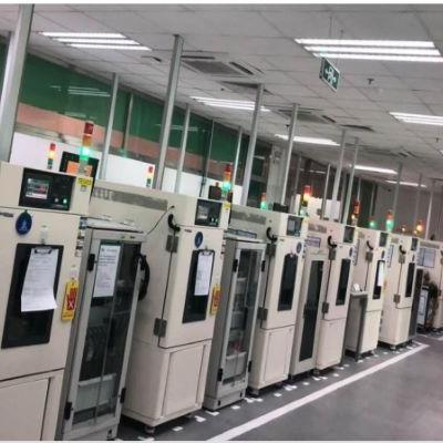
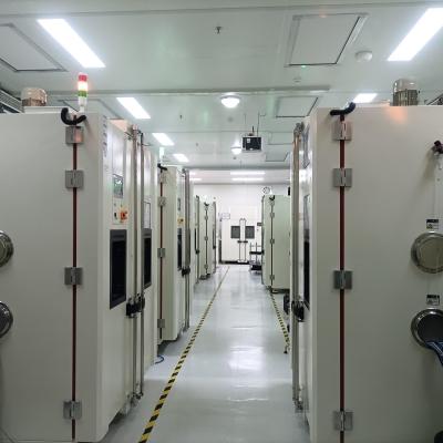
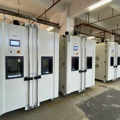
La prueba del ciclo de temperatura es uno de los métodos más utilizados para la prueba de confiabilidad y vida útil de materiales de soldadura sin plomo y piezas SMD. Evalúa las piezas adhesivas y las uniones de soldadura en la superficie de SMD, y causa deformación plástica y fatiga mecánica de los materiales de las uniones de soldadura bajo el efecto de fatiga del ciclo de temperatura fría y caliente con variabilidad de temperatura controlada, para comprender los peligros potenciales y los factores de falla. de uniones de soldadura y SMD. El diagrama de cadena tipo margarita está conectado entre las piezas y las uniones de soldadura. El proceso de prueba detecta el encendido y apagado entre líneas, piezas y uniones de soldadura a través del sistema de medición de rotura instantánea de alta velocidad, que satisface la demanda de pruebas de confiabilidad de conexiones eléctricas para evaluar si las uniones de soldadura, bolas de estaño y las piezas fallan. Esta prueba no es realmente simulada. Su propósito es aplicar una tensión severa y acelerar el factor de envejecimiento en el objeto que se va a probar para confirmar si el producto está diseñado o fabricado correctamente y luego evaluar la vida útil de la fatiga térmica de las uniones de soldadura de los componentes. La prueba de confiabilidad de la conexión eléctrica de ruptura instantánea de alta velocidad se ha convertido en un eslabón clave para garantizar el funcionamiento normal del sistema electrónico y evitar la falla de la conexión eléctrica causada por la falla del sistema inmaduro. Los cambios de resistencia durante un corto período de tiempo se observaron bajo cambios acelerados de temperatura y pruebas de vibración.
Objetivo:
1. Asegurar que los productos diseñados, fabricados y ensamblados cumplan con los requisitos predeterminados.
2. Relajación de la tensión de fluencia de la junta de soldadura y falla por fractura SMD causada por la diferencia de expansión térmica
3. La temperatura máxima de prueba del ciclo de temperatura debe ser 25 ℃ menor que la temperatura Tg del material de PCB, para evitar más de un mecanismo de daño del producto de prueba sustituto.
4. La variabilidad de temperatura a 20 ℃/min es un ciclo de temperatura, y la variabilidad de temperatura por encima de 20 ℃/min es un choque de temperatura
5. El intervalo de medición dinámica de la junta de soldadura no supera 1 min.
6. El tiempo de residencia a alta y baja temperatura para la determinación de fallas debe medirse en 5 golpes.
Requisitos:
1. El tiempo de temperatura total del producto de prueba está dentro del rango de la temperatura máxima nominal y la temperatura mínima, y la duración del tiempo de residencia es muy importante para la prueba acelerada, porque el tiempo de residencia no es suficiente durante la prueba acelerada. , lo que hará que el proceso de fluencia sea incompleto
2. La temperatura residente debe ser superior a la temperatura Tmax e inferior a la temperatura Tmin
Consulte la lista de especificaciones:
IPC-9701, IPC650-2.6.26, IPC-SM-785, IPCD-279, J-STD-001, J-STD-002, J-STD-003, JESD22-A104, JESD22-B111, JESD22-B113, JESD22-B117, SJR-01
Módulos solares de CA y microinversores 1La potencia de salida total del panel de células solares se reduce considerablemente, principalmente debido a algunos daños en el módulo (granizo, presión del viento, vibración del viento, presión de la nieve, rayos), sombras locales, suciedad, ángulo de inclinación, orientación, diferentes grados de envejecimiento, pequeñas grietas... Estos problemas provocarán una desalineación de la configuración del sistema, lo que dará como resultado defectos de eficiencia de salida reducidos, que son difíciles de superar con los inversores centralizados tradicionales. Relación de costo de generación de energía solar: módulo (40 ~ 50%), construcción (20 ~ 30%), inversor (
Módulos solares de CA y microinversores 2Especificación de prueba del módulo de CA:Certificación ETL: UL 1741, Estándar CSA 22.2, Estándar CSA 22.2 No. 107.1-1, IEEE 1547, IEEE 929Módulo fotovoltaico: UL1703Boletín: 47CFR, Parte 15, Clase BClasificación de sobretensión: IEEE 62.41 Clase BCódigo Eléctrico Nacional: NEC 1999-2008Dispositivos de protección de arco: IEEE 1547Ondas electromagnéticas: BS EN 55022, FCC Clase B según CISPR 22B, EMC 89/336/EEG, EN 50081-1, EN 61000-3-2, EN 50082-2, EN 60950Microinversor (Microinversor): UL1741-calss ATasa típica de falla de componentes: MIL HB-217FOtras especificaciones:IEC 503, IEC 62380 IEEE1547, IEEE929, IEEE-P929, IEEE SCC21, ANSI/NFPA-70 NEC690.2, NEC690.5, NEC690.6, NEC690.10, NEC690.11, NEC690.14, NEC690.17, NEC690 .18, NEC690.64Especificaciones principales del módulo solar de CA:Temperatura de funcionamiento: -20 ℃ ~ 46 ℃, -40 ℃ ~ 60 ℃, -40 ℃ ~ 65 ℃, -40 ℃ ~ 85 ℃, -20 ~ 90 ℃Voltaje de salida: 120/240V, 117V, 120/208VFrecuencia de potencia de salida: 60HzVentajas de los módulos de CA:1. Intente aumentar la generación de energía de cada módulo de potencia del inversor y realice un seguimiento de la potencia máxima, debido a que se realiza un seguimiento del punto de potencia máxima de un solo componente, la generación de energía del sistema fotovoltaico se puede mejorar considerablemente, que se puede aumentar en un 25%. .2. Ajustando el voltaje y la corriente de cada fila de paneles solares hasta que todos estén equilibrados, para evitar desajustes en el sistema.3. Cada módulo tiene una función de monitoreo para reducir el costo de mantenimiento del sistema y hacer que la operación sea más estable y confiable.4. La configuración es flexible y el tamaño de la célula solar se puede instalar en el mercado doméstico de acuerdo con los recursos financieros del usuario.5. Sin alto voltaje, más seguro de usar, fácil de instalar, más rápido, con bajos costos de mantenimiento e instalación, reduce la dependencia de los proveedores de servicios de instalación, de modo que los propios usuarios puedan instalar el sistema de energía solar.6. El coste es similar o incluso inferior al de los inversores centralizados.7. Fácil instalación (el tiempo de instalación se reduce a la mitad).8. Reducir los costos de adquisición e instalación.9. Reducir el costo total de la generación de energía solar.10. Sin programa especial de cableado e instalación.11. La falla de un solo módulo de CA no afecta a otros módulos o sistemas.12. Si el módulo es anormal, el interruptor de alimentación se puede cortar automáticamente.13. Para el mantenimiento sólo se requiere un simple procedimiento de interrupción.14. Puede instalarse en cualquier dirección y no afectará a otros módulos del sistema.15. Puede llenar todo el espacio del escenario, siempre y cuando se coloque debajo de él.16. Reducir el puente entre la línea CC y el cable.17. Reducir los conectores DC (conectores DC).18. Reducir la detección de fallas a tierra de CC y configurar dispositivos de protección.19. Reducir las cajas de conexiones de CC.20. Reducir el diodo de derivación del módulo solar.21. No es necesario comprar, instalar ni mantener inversores grandes.22. No es necesario comprar pilas.23. Cada módulo está instalado con un dispositivo antiarco que cumple con los requisitos de la especificación UL1741.24. El módulo se comunica directamente a través del cable de salida de alimentación de CA sin configurar otra línea de comunicación.25. 40% menos componentes.
Módulos solares de CA y microinversores 3Método de prueba del módulo de CA:1. Prueba de rendimiento de salida: el equipo de prueba del módulo existente, para las pruebas relacionadas con el módulo no inversor.2. Prueba de estrés eléctrico: realice una prueba de ciclo de temperatura en diferentes condiciones para evaluar las características del inversor en condiciones de temperatura de funcionamiento y temperatura de espera.3. Prueba de estrés mecánico: descubra el microinversor con adherencia débil y el condensador soldado en la placa PCB4. Utilice un simulador solar para las pruebas generales: se requiere un simulador solar de pulso en estado estacionario de gran tamaño y buena uniformidad.5. Prueba en exteriores: registre la curva I-V de salida del módulo y la curva de conversión de eficiencia del inversor en un ambiente exterior6. Prueba individual: cada componente del módulo se prueba por separado en la sala y el beneficio integral se calcula mediante la fórmula7. Prueba de interferencia electromagnética: debido a que el módulo tiene el componente inversor, es necesario evaluar el impacto en EMC y EMI cuando el módulo funciona bajo el simulador de luz solar.Causas comunes de falla de los módulos de CA:1. El valor de resistencia es incorrecto.2. El diodo está invertido.3. Causas de falla del inversor: falla del capacitor electrolítico, humedad, polvoCondiciones de prueba del módulo de CA:Prueba HAST: 110 ℃/85% R.H./206 h (Laboratorio Nacional Sandia)Prueba de alta temperatura (UL1741): 50 ℃, 60 ℃Ciclo de temperatura: -40℃←→90℃/200cicloCongelación húmeda: 85 ℃/85 % H.R.←→-40 ℃/10 ciclos, 110 ciclos (prueba Enphase-ALT)Prueba de calor húmedo: 85 ℃/85% R.H/1000 hMúltiples pruebas de presión ambiental (MEOST): -50 ℃ ~ 120 ℃, vibración 30G ~ 50GResistente al agua: NEMA 6/24 horasPrueba de rayos: sobretensión tolerada hasta 6000 VOtros (consulte UL1703): prueba de pulverización de agua, prueba de resistencia a la tracción, prueba antiarcoMTBF de módulos relacionados con energía solar:Inversor tradicional 10 ~ 15 años, microinversor 331 años, módulo fotovoltaico 600 años, microinversor 600 años[futuro]Introducción del microinversor:Instrucciones: Micro inversor (microinversor) aplicado al módulo solar, cada módulo solar de CC está equipado con un, puede reducir la probabilidad de que se produzca un arco, el microinversor puede pasar directamente a través del cable de salida de alimentación de CA, comunicación de red directa, solo es necesario instalar una fuente de alimentación. Línea Puente Ethernet (Puente Ethernet Powerline) en el enchufe, no es necesario configurar otra línea de comunicación, los usuarios pueden a través de la página web de la computadora, iPhone, Blackberry, tableta... Etc., observar directamente el estado operativo de cada módulo. (salida de potencia, temperatura del módulo, mensaje de falla, código de identificación del módulo), si hay una anomalía, se puede reparar o reemplazar inmediatamente, para que todo el sistema de energía solar pueda funcionar sin problemas, porque el micro inversor está instalado detrás del módulo. por lo que el efecto de envejecimiento de la radiación ultravioleta en el microinversor también es bajo.Especificaciones del microinversor:UL 1741 CSA 22.2, CSA 22.2, No. 107.1-1 IEEE 1547 IEEE 929 FCC 47CFR, Parte 15, Clase B Cumple con el Código Eléctrico Nacional (NEC 1999-2008) EIA-IS-749 (prueba de vida útil de aplicaciones principales corregida, especificación para uso de condensadores)Prueba de microinversor:1. Prueba de confiabilidad del microinversor: peso del microinversor +65 libras *4 veces2. Prueba de impermeabilidad del microinversor: NEMA 6 [funcionamiento continuo de 1 metro en agua durante 24 horas]3. Congelación húmeda según el método de prueba IEC61215: 85 ℃/85 % H.R.←→-45 ℃/110 días4. Prueba de vida útil acelerada del microinversor [110 días en total, prueba dinámica a potencia nominal, ha garantizado que el microinversor pueda durar más de 20 años]:Paso 1: Congelación húmeda: 85 ℃/85 % H.R.←→-45 ℃/10 díasPaso 2: Ciclo de temperatura: -45 ℃ ← → 85 ℃/50 díasPaso 3: Calor húmedo: 85 ℃/85 % H.R./50 días


 Consigue una cotización
 Red IPv6 compatible